%20small.png)
DDS Integration Setup
- Leanne Weaver
- Nov 18, 2024
- 4 min read

Updated: Jul 30, 2025
Scope of the Export
Current limitations and known issues can be found in the components list in the Download Manager; hover over the icon to view the warning. The icon denotes the status of each warning; blue circles indicate info, yellow triangles indicate a warning, and red circles indicate an issue.

Any missing or malformed attributes, quality control warnings, or other data issues will be communicated in a DDS Export Warnings dialog upon export.

Because make ready and pole loading will be done in DDS, no make ready is exported
Review the What Has Updated section to see what changes we've recently made
Requirements
Access to DDS on an AEP VDI
Parallel Pole Loading Exports with Katapult Pro (or External Pole Loading for those with legacy subscriptions)
Model Setup
If you have an existing model without the DDS integration set up yet, but would like to include it, go to the following Add DDS Integration To Existing Model section. If you are creating a brand new model and would like to include DDS integrations, go to the New DDS Model Setup section. If you would like to update an existing model with DDS integration to the latest version, please reach out to support@katapultengineering.com.
Add DDS Integration To Existing Model
Open your existing model.
Click "Import From Catalog" at the top and select the DDS - AEP Catalog.

Import the "Wire Name" and "Wire Overhead Type" attributes from the "Attributes" portion of the catalog.

Open the latest version of our DDS Specs (i.e. DDS - AEP 2025-05 Specs) and import the "Conductor Bank" attribute; (optionally,) you can import the "Wire Spec," "Bundle Components," and "Messenger Spec" attributes that have been updated with more specifications available.

(Optional.) Go back to your model and open the "Photo Routines" to add the "Conductor Bank" attribute to all of your existing DDS Framing Photo Routines. (This way you won't need to manually add the attribute each time you insert the DDS Framing chip. Make sure you fill out the "Conductor Bank" during the photo annotation process.)
Find the the "DDS Bundles" (underneath "Exports") to configure any needed DDS Bundles.

Your model is now ready for use. Keep moving ahead to the Job Setup section of this manual.
New DDS Model Setup
Create a blank model for the jobs that will be exporting DDS. (Pro Tip: You can copy an existing model by creating a blank model and importing the one you want to copy. If you do this, go back to "Add DDS Integration To Existing Model" for your copied model.)
Import the AEP DDS core catalog (DDS - AEP).

Import the latest AEP DDS Specs catalog as well (i.e. DDS - AEP 2025-05 Specs).
Communications cables will need a wire spec and bundle spec combination. Some bundle specs will be included in the DDS catalog you imported; if you need additional bundle specs, these can be created in the Model Editor under Exports. Find the DDS Bundles tab to start creating those bundles.

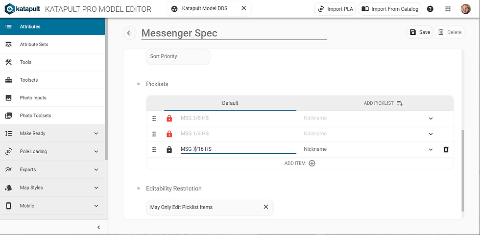
(Optional.) If you need additional messenger specs (or other component specs), find the spec in the Attributes section of the Model Editor and add the spec you need in the picklist at the bottom.
Your model is now ready for use. Keep moving ahead to the following Job Setup section of this manual.
Job Setup
You’ll want to prepare the job the way you would for any pole loading analysis. You’ll need to add specs for com wires, power, anchors, and poles, along with any hardware on the poles. Use the DDS Framing Photo Inputs to correctly annotate the framing on each pole. Use Hardware Details to link guys to anchors, enter equipment specs and angles, and check for any missed specs. More details on preparing a job for pole loading can be found in our Preparing Jobs for External Pole Loading manual.
What Has Updated
Conductor Banks are now included in our DDS Integration
The export now looks for the Conductor Bank attribute value that's set on the DDS Framing photo chip on either side of a connection to determine the name of the Conductor Bank for a given group of conductors.
This will facilitate better transfer of secondary conductors into DDS and fewer match questions for primary conductor banks.
If you don't have the Conductor Bank attribute present on your DDS Framing chip, the export will still include the conductors in that span, but you will see a warning.
If you have the Conductor Bank attribute but the values on either side of the span don't agree for a given group of conductors (as linked by '_routine_instance_id'), the export will warn you and it will not include the conductors in that span.
You will find Conductor Heights in our updated catalog
We now specify the start and end connection heights for each conductor in a conductor group
This should ensure the correct heights are imported into DDS
If this isn't the case, please reach out to support@katapultengineering.com with an example job and pole.
You have more control with Communication Bundles
Use any wire spec name (it doesn't have to match an existing AEP specification)
Specify the Wire Name (which is essentially the communication conductor bundle name in DDS)
We generally recommend using OH-AUX-MSGR
Specify the Wire Overhead Type, i.e. Lashed, SelfSupported, or Conductor
With Lashed you can set:
Messenger Spec (picklists come from Messenger Spec)
Lashed Bundle Options
Specify Components (this lets you choose specific cable specs, i.e. CATV 218/264, COAX 1/2, TEL 1800 PR, etc.)
Specify Diameter & Weight (this allows you to directly edit the diameter and weight of the lashed bundle)
If you select SelfSupported, that is the extent of available options
Pro Tip: this option would typically be used with cables such as OH-CATV, ADSS
Same thing with the Conductor option.
This newer structure allows the communication conductors to better attach to the structure in DDS, allowing you to edit the messenger and lashed cables (if applicable).
Include proposed cables and elevation in export
In the download manager, you can check the option to include proposed cables in your download
To include elevation, fill out the "Measured Elevation" attribute on your poles and check the "Include Elevation" option when exporting
More equipment is available for export
Currently you can export antennas, capacitors, reclosers, regulators, risers, streetlights, switches, termination banks, and transformers


Comments