%20small.png)
Katapult Pro Integrated Pole Loading Manual
- Leanne Weaver
- Sep 12, 2023
- 12 min read

Updated: Oct 21, 2025

Content Links
Overview
Katapult Pro Integrated Pole Loading is a real-time pole loading analysis software built into the Katapult Pro interface. While external PLA exports are still available, Katapult Pro Integrated Pole Loading gives real-time, accurate results for existing and proposed conditions without having to leave the platform or own a seat of a third-party software. This tool ensures better Make Ready Engineering calls.

When you use this pole loading tool with the pole height photo opened, a percentage will display in the top left corner that shows the load on your pole using your selected NESC Construction Grade.

If the pole loaded is a steel pole, the terminology related to the loading percentage (such as using "moment" instead of "stress," as shown in the screenshot above,) will be adjusted to account for the unique internal force calculations and structural behavior of steel poles (since they differ from those of wooden poles).
Combining this pole loading tool with the make ready tools in Katapult Pro, you can diagnose loading failures in real-time and see how proposed attachments change the current state of the pole.


From the three dot menu (next to the load percentage), you can view more details of the loading analysis including warnings, wind direction, and a download that contains all the details of the forces affecting the pole as well as the warnings shown in the details panel.

With loading analysis of steel poles, you will see "Moment Loading Percentage" instead of "Pole Stress Loading Percentage." You'll still have the "Pole Buckling Percentage" and "Wind Direction" underneath that.


There are also slight changes for the PLA Report for steel poles than for wooden poles. The first page of the PLA Report for steel poles will show the worst moment load vs. wind direction instead of max pole stress vs. wind direction. For the Worst Wind Direction Pole Results page, for steel poles, it'll provide the net moment vs. height instead of the max von Mises stress vs. height.
How to Use
The following section covers the basics of the tools you need to effectively use Katapult Pro Integrated Pole loading, as well as how to use them to get your pole loading results. Your workflow may have additional steps or modifications, but this should cover all the basics to get you started.
Integrated Pole Loading Tools
Once all the attachments are traced on the pole, you'll want to click on the following tools to ensure all specs are input for loading analysis. These tools will add their details to all poles in a job.
Com Wire Spec. If using the diameter midspan feature (where the you set the diameter in the

three panel Cable Trace view on the midspan), this tool inserts wire specs for communication attachments. It also adds the down guy spec. If you do not use the diameter feature, make sure to insert a wire spec for communication attachments. *This tool is configured to work with our catalogs. If you modify the wire specs from our catalogs (including adding new ones) or want to use wire specs from you catalogs or client files, please reach out to support@katapultengineering.com to help configure this tool for you.

Hardware Details. Prompts user for power wire, down guy, and equipment specifications.

Calc Bearings. Determines angles of insulators based on traced directions.

Insert Anchor Spec. Adds Anchor Spec needed for pole loading.

Pole Spec. This should have been added in extraction, under the Pole Info, but will also be important for loading.
These are a few other attributes that you will need on a case-by-case basis:
Wire_tension. Added to a midspan marker to set a wire to slack tension or full tension. Full tension is assumed by default.
Custom_tension. Added to a span marker to set a custom tension value in pound-force.
Point_load_end. Added to one end of a pole-to-pole guy on its marker. This attribute signifies the "load" end of the guy, and the other end is assumed to be the "support" end.
There are also some unique build cases that require some additional steps:
Push braces. Set the node type to "pushbrace," and the connection type to "pushbrace" to have your pole load with the brace against it.
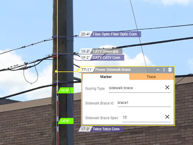
Sidewalk brace. Add a guying marker to the pole with the guying type "sidewalk brace." This will give 2 attributes to fill out. Sidewalk Brace ID will let you link your down guys to the brace. Fill out an ID you would like to use to identify the sidewalk brace (i.e. brace1), then edit your down guy marker and add the Sidewalk Brace ID to it as well. Copy and paste whatever ID you created (i.e. brace1) into the down guy, and the brace and guy will now be linked for loading. Sidewalk Brace Spec lets you pick the length of the brace.

Crossovers. Draw spans that are not in crossovers as references.

Place anything that is on an actual crossover on the crossover span. Make sure the node type is "crossover"

Place all traces in the crossover on a three bolt insulator. If they are all sharing a bolt, you can have them all in the same three bolt marker. For instance, if it is an aerial cable becoming an overhead guy, they can both be on a three bolt insulator.

Mark overhead guys as strands and it will balance loads properly during loading.
If there are two or more crossovers between poles, only the first one (nearest to the pole you are loading) will be used in the analysis.

Custom equipment. This can be used on a case-by-case basis for equipment that doesn't have a model. Create a Custom Equipment height marker and make sure to fill in the following values:
Bearing. The direction that the bolt of the equipment is facing
Cross-sectional Height. The height of the equipment in inches. (See image below.)
Horizontal Offset. The distance between the center of the pole and the center of the mass of the equipment in inches. (See image below.)
Cross-sectional Width. The width of the equipment in inches. (See image below.)
Cross-sectional Depth. The depth of the equipment in inches. (See image below.)
Equipment Weight: the weight of the equipment in pounds.
Shape Factor. Describes the shape of the equipment for wind loading (i.e. 1.0 cylindrical, 1.6 flat structure (non-lattice), 3.2 sum of faces flat lattice structure, and 2.0 sum of faces round lattice structure)

*If you can't find the Custom Equipment equipment type when you place an Equipment marker, your model might not be set up correctly for Integrated Pole Loading. Reach out to support@katapultengineering.com for help.
Running Loading Analysis
Once the above steps are complete and all necessary data is filled out for pole loading, you are ready to begin the loading analysis.

To load your pole, select it and add the "Load Case" attribute and select a loading grade.

Click the "Pole Loading View" button on the top ribbon of the screen. This view can be toggled on and off at any time using this button. You can also toggle on the "Make Ready View" button to view the pole with make ready changes instead of its current state.
At the top left corner of the photo of the pole, one or more percentages appears, indicating the load occurring on the pole, down guys, and anchors.

Clicking the three dot menu, the "Show Details" will allow you to see details of the loading analysis including warnings, wind direction, and analysis information.
At the bottom of the "Pole Loading" details, there is a "Download PLA Report" button, which provides a fully detailed PDF document of the analysis and specifications of the pole.

In the same menu, you'll find the "Arm Offset Diagram." In a new tab, it will open a diagram detailing the arm offset measurement used in the integrated pole loading analysis (seen below).

Toggling the "Make Ready" view will show the Proposed loading result as opposed to the existing loading result.

The image above shows the pole being replaced with a larger pole both in height and class, and the resulting loading percentage lowers.

If the percentage turns red or yellow, there is a warning that could be preventing the pole from loading.
The "Pole Loading" details will list what data is missing and is needed in order to load the pole. In the picture above, the pole-to-pole guy has no point load end.

You can also deselect companies from the pole to run load analysis as if they were not attached. In the three dot menu beside the percentage, there is another option titled "Company Filters." From here, a checklist of the parties attached to the pole will appear.

Toggling the checkboxes on and off will automatically recalculate the load with only the selected attachments.
Additionally, individual markers can be marked to be skipped by the loading engine by adding the "PLA Ignore" attribute. These markers will be grayed out and not considered for the analysis of the pole.
Bulk Pole Loading Tool
The Bulk Pole Loading Tool allows you to run pole loading on several poles at once. First, you'll want to make sure this tool has been added to your Job Model and placed in a Toolset of your choosing.

Whoever has permissions to edit the Job Model will need to navigate to the Model Editor, open the appropriate model, click the "Import From Catalog" in the toolbar at the top of the page, open the "Power Tools" catalog, look under the "Tools" section (in blue), and click the "+" icon next to "Bulk Pole Loading" to add that tool to the Job Model. Don't forget to add it to a Toolset from the Toolsets section.

Whoever is using the tool will need to make sure they're using the appropriate toolset on the Maps page. The tool has the same icon as the Pole Loading View button and the Pole Loading details underneath the pole height photo and is orange. Before using this tool, make sure all the poles you want to load in bulk have a "Load Case" attribute with a load case selected.

When you run the tool, you will be prompted to draw a polygon around the poles you want to load. "Select All" will select all poles in the job.

Next you will choose if you want to analyze the pole's load in its existing state or in its proposed state that it would be in if all make ready calls were performed properly. Then you can decide whether or not you want to include an attribute if it passes and/or if it fails, as well as what that attribute should be and what value it has should the pole pass or fail.
Once "Load" is clicked, there will be a quality control window detailing any errors that occurred, and which poles they occurred with (similar to the quality control window you would see when the Photo Association tool is run).
Multi-Load Ability
You can add multiple load cases to a pole to be run at once. Simply add the Load Case attribute to the pole again, selecting the load case you want to include.

When you load the pole, the percentage in the top right of the page will first display whichever load case has the worst loading result. Click the arrow next to the load case to switch between the load cases on the pole.

Regardless of which load case is selected in that percentage in the top right corner of the photo, all loading results for each load case will be displayed in the Pole Loading section at the bottom of the photo. Again, the first load case displayed in the list will be the worst result.
3D View Page
With a 3D Model of the pole available, this helps you see how the software renders the pole(s) based on the date you've entered. This can also help easily identify any information that may have been incorrectly entered by mistake. Ensure integrated pole loading is set up correctly in your job model before using the 3D View page. To open a 3D model of a pole, open its Node Info panel.

Towards the top, click the three-dot menu to open the menu with "3D Model" as an option. When you click on this option, it will open the 3D View page in a new tab. (Similar to the Cable Tracing view, only one tab is ever open for this page. If you were to click on the 3D Model option again, it would bring focus back to that one tab.)

The 3D View page will always show any and all poles within the job (where the Node Type is "pole"). When you open this page from a pole, it will focus on the model of that specific pole. If you want to change focus to a different pole, click on another pole in this 3D View page or use the Search Poles/Location dropdown at the top of the page.

This is in sync with the Maps page, so whenever you select a different pole, that pole will also be selected in the Maps page automatically and vise versa. You can turn off this synchronization by clicking the "Sync with Map Page" toggle in the top right.

Similar to Streetview, the 3D View page will place a pegman on the Maps page, but this one is blue (instead of yellow). This can be moved around to change the 3D View - mostly how close/far away from the pole your view will be. The arrow on the pegman will always point at the pole in focus, whether this pole was selected on the Maps page or the 3D View page. This blue pegman will not show up if the "Sync with Map Page" toggle is turned off.
You can also change the view of the model from the 3D View page. Scroll up to zoom in (with your mouse as the focus of the zoom) and scroll down to zoom out. If you click and drag the map on the 3D View page, you can change the angle of the 3D model. Hold the "Ctrl" key while clicking and dragging the model to move it up, down, left, and right.

While inspecting a pole's 3D model, you can click on the pole itself to view its information, which may include the pole owner, pole spec, and tag text if those values for the pole tag and pole spec attributes have been filled out.

Clicking on a cable will give you information such as the cable company, the cable type, and wire spec (if those attributes are filled out). The heights of the cable on the pole(s) and midspan(s)/section(s) will also appear along the entire cable's trace in the job.

This 3D View page has a Make Ready View and Pole Loading View just like the Maps page. The Make Ready View, when turned on, will show a 3D model of the pole's proposed state.

If anything is moved, added, or removed, this will be reflected in the Make Ready View when it's turned on. The proposed cable is shown in blue.

When the Pole Loading View is turned on, the wind direction (both the worst wind direction, in blue, and the failure direction, in red,) is shown at the base of the pole. The loading percentage of stress on the pole is shown above the pole, above its SCID. If the pole passes the pole loading analysis, the percentage is shown in green.

If the pole is failing, the percentage is shown in red. You'll notice the stress on the pole is shown is yellow and red in the areas of the pole that are experiencing that stress. (This is also shown even if the pole is passing.)

If there is a red exclamation mark above the pole, this means that a loading case has not been selected and therefore the pole cannot be loaded.

If the pole is loaded but has other warnings, the percentage above the pole will show in orange, and clicking on the pole will show these warnings (along with the pole information).
Rendering The Pole

If there is a node that has a Node Type of "pole" but has no annotations, only this pink, bare pole will be modeled. Click on the pole to open the Information and any Warnings.
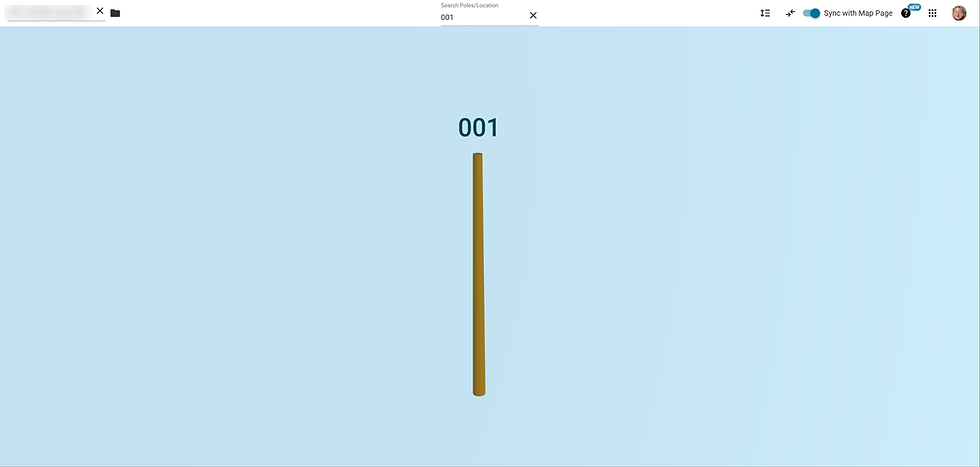
Once the pole height photo is calibrated and a pole height marker is placed, the pole's 3D Model will solidify the pole and it will turn brown. If it has a SCID, this will show up above the model of the pole.

Any arms and equipment (such as drip loops, transformers, capacitors, switches, cutouts, streetlights, risers, reclosers, and cabinets) annotated on the pole will not be modeled until the equipment bearing is filled out.

Some equipment, such as transformers, will need a spec filled out before being fully rendered because the spec will be needed to determine the dimensions.

The ground is rendered when poles have their Google Elevation set, which can be done automatically for all poles with the Google Elevation tool.
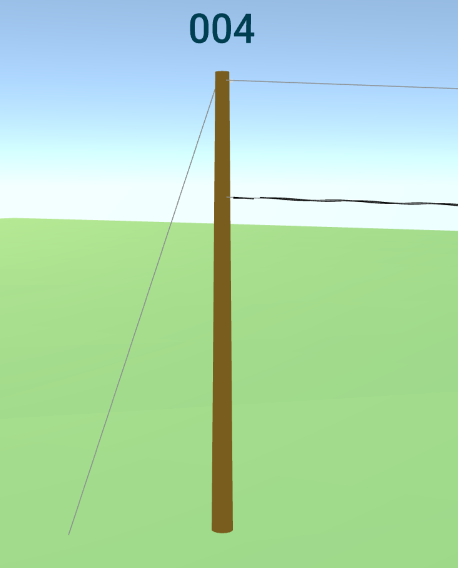
Cables on poles aren't rendered until they're traced in a midspan. In the example above, the cables are drawn in a midspan to the right but have not yet been rendered for the midspan to the left because they have not been traced to that midspan yet. If the traced cables do not have a height, whether measured or manually entered, their default height will be 0.

Once cables are traced and their wire spec is filled out, they will be rendered in the 3D Model View. The thickness of the communication cables are based on the diameter that was entered.

Down guy annotations must be linked to an anchor node (with a down guy connection to the pole that the down guy is attached to). The software will take the bearing of the anchor to determine the bearing of the down guy, as well as the lead length and anchor location to properly render the down guy.
Once you enter the wire spec of the down guy, this will also further define the rendering of the down guy. The elevation of the anchor is also taken into calculation when determining where the down guy should end. More specifically, the software will use the pole's position in addition to any anchor offset that has been inputted for that anchor.

Reference poles are also rendered; however, these poles are faded out more to visually communicate that they are only for reference. This will also be communicated through the Information bubble that appears when you click on the pole.
Customizing Your Model
You can customize your model for Integrated Pole Loading under the "Pole Loading" option in the Model Editor menu. The Pole Loading section of the Model Editor Manual covers all these options.
Current Limitations
Concrete poles
Multi-pole structures
Individual Arm load analysis
Individual Insulator load analysis
Automatic calculation of tensions for bare strands (where "wire_type" = Strand Only)
Elevation changes between poles
Arm offsets on adjacent poles are not accounted for
For situations where these cases are required, we recommend using our PLA exports to load specific poles from a different engine.
Thanks for reading! Contact support@katapultengineering.com with any questions. How can we improve our documentation? Leave a comment below!


Comments