%20small.png)
Katapult Pro Model Editor Manual
- Adam Schmehl
- Oct 4, 2021
- 41 min read
Updated: Oct 21, 2025

Content Links
The Model Editor is a powerful tool to help your team customize and configure your Models to meet your clients’ or markets’ needs. Understanding how to use the Model Editor will streamline your workflows and put your team in a position to deliver a superior product to your competitors.
*Restricting edit access to your Model so that only company admins have edit access can be configured under "Model Options" in the Model Editor with the toggle for "Only Allow Admins to Edit This Model."
*Editing restrictions for specific users can be done in the Admin Page under the user's "Other Permissions."

You can access the Model Editor anytime from the App Tray at the upper right corner of your screen. Clicking Model Editor will open the page in a new tab. You can also access it at katapultpro.com/model-editor.
Models: Existing Or New

When you open up the Model Editor, you can choose an existing Model or create a new one. If you choose to create a new one, click the blue "+" button. Then enter the name for your model when prompted.

Next, if you have our Data Collection offering, you will see a choice between the Default Setup or Create Blank Model. We recommend choosing Default Setup.

Otherwise you will choose between setting up the model through our guided setup or creating a blank model. When you choose “guided” (recommended), you will be prompted to enter relevant information and upload files such as pole loading Client Files and Catalogs if applicable.
Creating A Model: Guided Setup
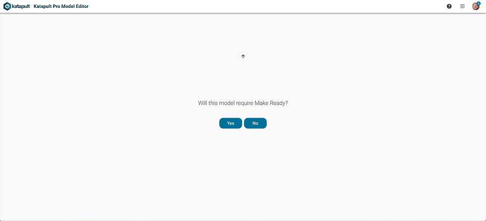
The first question you must answer is if your model will require Make Ready engineering. If you click "No," it'll move on to the next question.

However, if you answer "Yes" to requiring Make Ready, you'll be prompted to choose a set of make ready rules to build out your model. You have the choices NESC and GO 95.

The next question you will be asked is if the model requires Pole Loading. If you answer "No," your model will be created.

If you answered yes, you'll be directed to the PLA setup. There are four checkbox options:
Include Integrated Pole Loading. (If you don't see this option but would like to use it, you may want to reach out to our sales team at sales@katapultengineering.com.) If you want to use this model for Integrated Pole Loading in addition to external pole loading, check "Include Integrated Pole Loading" and read the setup documentation corresponding with whichever third-party platform you will be using for external pole loading to ensure your client file is formatted as it needs to be.
Skip Messengers (O-Calc and Spida Models). If you checked "Include Integrated Pole Loading," you will want to make sure that "Skip Messengers..." is also checked.
Pass Tensions Through to Export (O-Calc Models). We recommend keeping this checked at all times. If you have questions regarding this specific option, feel free to reach out to support@katapultengineering.com.
Clear Existing Pole Loading Specs. Since you are creating a model, you may leave this unchecked. This same screen will appear if you were to later update your client file and clicked "Import PLA" in an existing model to import the updated client file. When this option is checked, it'll clear out the outdated Pole Loading Specs and import the updated Pole Loading Specs from the client file.
Once you have set those four settings appropriately, you may drag and drop your client file in the white square with the "+" or click the gray button in that spot to browse your file explorer.

Once the client file is uploaded, you will be asked to review your catalog before continuing. You can click the downward arrow next to each item to review the options you are carrying over into this model. Uncheck anything you want to exclude.

After all questions have been fully answered, the guided portion of the setup is complete and your model will be created in a few moments. (If you chose the "Create Blank Model" option, you will immediately see this load page.)

The platform will notify you that your model was created successfully and display this Success view.
Importing Into A Model

Once you have created a new job model or have selected an existing one, you can then begin editing your model.
You can copy an existing model into a new model by clicking “Import From Catalog" in the upper right corner, and then scroll down to select an existing model, denoted by a circular icon with three dots. You can copy the entire model by clicking the gray "+ Import Entire Model" button or copy individual pieces of the model by clicking the dark gray "+" next to the piece you are considering copying (whether it be attribute(s), tool(s), or so forth).
There are also Katapult Pro catalogs available to import any combination of data that your model may need. For example, the Data Collection catalog provides different attributes, tools, toolsets, photo inputs, photo toolsets, quality control modules, and model options to assist with data collection. We'll explore each component of the Model Editor (attributes, tools, toolsets, etc.), so keep reading!
Transparency On Model Edits
In the Model Editor, for items like attributes, tools, photo inputs, photo routines, etc., the source of any changes will be recorded along with the date the changes were made.

In the above screenshot, below the name of the Company attribute, there's a note saying that this attribute has been manually updated by a user on 7/26/2025.
Attributes

The first section of the Model Editor is Attributes. Attributes are pieces of information which determine the properties of a field in your database. Here, you can search for or create a new attribute, or view your entire list of Attributes for this Model. The red lock icon indicates a locked attribute which cannot be edited manually, and the “list+” icon (as seen to the left of the "Cable Type" attribute in the above screenshot) indicates an attribute with a picklist. Click any attribute to edit its existing structure, or the plus ("+") button to create a new attribute. (Any attribute with a lock icon, like "Bearing" in the above screenshot, are attributes that are locked down and cannot be edited.)

Attributes can be many different types:
Single Line Text - One-line text field where text values can be entered.
Hyperlink - Input will be treated as a web address and opened in a new tab when clicked.
Single Line Text with Commit - Same as single line text, but includes an option to confirm or delete text entered.
Multi-Line Text - Multiple lines of text values can be entered.
Checkbox - True or False field, editable by checking or unchecking a box
Dropdown - Picklist that enables the correct value to be chosen from a list of options
Multi-Select Dropdown - Picklist that enables multiple values to be chosen from a list of options
Group - Groups attributes together at once so that adding one attribute to a node, section, or otherwise will add multiple values (i.e. Birthmark attribute adds Pole Height, Pole Class, and Pole Species to a node).
Table - Allows for multiple attributes to exist under one attribute, and have a subset of data within a table.
Date - Input is formatted as "mm/dd/yyyy." A Calendar icon is provided to assist entering a date; when clicked, you'll see a calendar with the current month selected.
File - This attribute type allows for a multitude of files and file types to be uploaded to wherever this attribute is kept. It can later be downloaded or deleted.

*If you selected any kind of text input as your attribute input type (i.e. single line text, single line text with commit, or multi-line text), you'll see the Placeholder Text step next. Whatever text you enter here will appear in gray in the input area when you add the attribute and don't have a value for it yet. This step is optional. Then you'll see the step for selecting what the attribute can be added to.

After selecting which type of attribute you would like to create (or entering the Placeholder Text if your attribute is a text input), select which items the Attribute can be added to. This could be Nodes (such as poles, anchors, crossovers, references, etc.) or Connections (such as aerial cables, overhead guys, slack spans, etc.) or Sections. You could also add the attribute to Photo Annotations, so it would appear on the Marker tab on a wire, insulator, or equipment during data processing in the Photos view while Cable Tracing. This could also be added at the Job level, where the attribute will be shown in the Job Settings panel. You can select any combination of these entities for your new attribute to be added to.

Next you'll have the option to choose an Attribute Group - a specific category located within the Node, Connection, or Section Info panel or Job Settings panel. You can choose existing groups, create your own, or skip this step altogether.
For any attribute that can be added to jobs, you will then have the choice of whether or not the attribute will show up when the user creates a job. (For some more detailed options when you choose to include the attribute in the job creation prompt, you can require the user to fill out the attribute, set the order it will show up if there are other job attributes listed in the job creation prompt, or setting the default value.)

In the above GIF, you'll see that once the job model is selected, a list of "Job Attributes" will appear at the bottom of the job creation prompt with our attribute.

In the fourth step, you can choose whether the attribute will be read-only or not by clicking the checkbox or clicking on "Yes" or "No." This means even users with write permissions won't be able to edit the attribute. For example, if you're importing external data into Katapult Pro that shouldn't be edited within the Maps page, you may want to make it a read-only attribute.
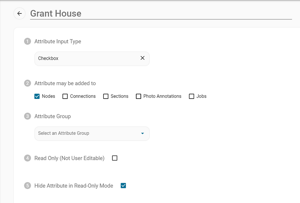
Answer the same way to whether or not the Attribute should be hidden when the job is in read-only mode (when the lock icon turns red and looks locked). This will hide the attribute from any external users with whom you share the job with read-only access.

Choose the priority the attribute should have when it comes to ordering it in the info panel or skip this step. The smaller the number, the higher the priority (i.e. 1 would be higher on the list than 2). This step is optional.

*For single line text attributes, after the Attribute Sort Priority, you'll reach a step called Mobile Assessment Validation Options. These options allow you to specify restrictions for the text input when entered via Mobile Assessments. The Numeric Input Only option, when checked, will apply the rule that only number can be entered when setting the attribute via mobile assessment. You can also specify the maximum number of characters that can be entered. Or, you can specify the exact number of characters that should be entered. The Regex Expression field is automatically filled based on your input for the previous options, so you don't have to worry about filling this out. However, it does exist as an advanced option should you have a specific Regex Expression for validating the attribute's input. Finally, the custom error message is what will be displayed if the fielder enters input that violates the validation you just set.

*If you chose for your attribute to be a dropdown (whether dropdown or multi-select dropdown), after the Attribute Sort Priority, you will see a step called Picklists. This is where you can enter the available options for users to choose the attribute's value from. You can categorize the values into several different picklists (i.e. for Node Type, 'new anchor' and 'existing anchor' options are held under the "Anchor" list, while options like 'pole,' 'building attachment,' and 'reference' are stored under the "Osp" picklist). This is not only to organize values, but in instances such as allowing a fielder to set the value for a dropdown attribute, you can limit their options to a specific picklist of values.
Click "ADD PICKLIST +" to get started. Once you've named the picklist, click "Create Picklist." Once you have at least one picklist, the "ADD PICKLIST+" button can be found at the end of the list of existing picklist(s).

*For multi-select dropdown attributes specifically, there is an Allow Duplicate Selections option followed by the Always Display Vertically (Sortable) option. Allow Duplicate Selections, when checked, will allow the user to select a value more than once. For example, the default 'Sizes of Dn Guys' attribute allows you to select a size (i.e. 6.6M) more than once in the case that there are several down guys with the same size.
For Always Display Vertically (Sortable), this option, when checked, will show the user's selected values in a vertical list where they can sort the order of values within the list. When this is not checked, the order of values selected won't be editable and the values will be listed horizontally and start a new row when that list gets too long.

*If you chose to create or edit a group attribute, you will have a step for deciding which attributes get added to this group. Here you can add as many attributes as you like. However, adding another group attribute here won't work. You'll have to individually add all the attributes that appear in the other group attribute in order for all of them to be added by this group attribute you are creating/editing. For example, we wouldn't be able to add the "Birthmark" group attribute to this "Pole Default Attributes" group attribute. We'd have to add "Pole Height," "Pole Class," and "Pole Species" individually to this "Pole Default Attributes" group attribute. When adding attributes to the group attribute, you can specify a default value for the attribute as well.

*For table attributes, there will be a Table Details step after the Attribute Sort Priority step. First, you'll see a checklist of options: Show Option to Duplicate, Show Option to Duplicate and Increment, Combine Similar Rows, Hide Header Rows, Hide Add New Rows, and Allow Horizontal Scroll.
Show Option to Duplicate

Details:
Checking the box for this option will display a "Duplicate" option. When the user clicks the pencil icon next to a row of the table to edit the item, an "Edit [Attribute]" window will open, and in the corner is a vertical three-dot menu from which this option can be selected.
When selected, the row will be duplicated, and the "Edit [Attribute]" window will display the data for that row in case any information needs to be changed slightly. (In this example, the Telco row is being copied and the wire spec is changed.) When all the information is correct, the user can click "Save."
Show Option to Duplicate and Increment

Details:
Similar yet different from the "Duplicate" option, when checking this option, you'll notice an additional column next to "Required" that says "+1." When checked, this means the attribute can be selected to be incremented. (In this example, the attribute that can be incremented by one is the "Position On Pole" attribute.)
As stated previously, when the user clicks the pencil icon next to a row of the table to edit the item, an "Edit [Attribute]" window will open, and in the corner is a vertical three-dot menu from which this option can be selected.
The user will be prompted to choose a field to increment and enter how many times they want to duplicate the rows.
At least one attribute must be checked in the "+1" column in order for the "Duplicate and Increment" option to work. (Checkbox attributes are not a valid candidate for incrementation.)
Note: numeric attributes are the best candidates for incrementation. For attributes with a purely numeric value, it will be incremented by 1. If it is purely alphabetic, it will take the last character and "increment" it by one (it'll replace it with the next character in terms of their ASCII codes).
Combine Similar Rows

Details:
The software will look for the same pieces of data so that duplicate results are not added, or so you do not have to worry about having to look for multiple attributes to get a total value. In the Model Editor, you will be prompted to add an attribute to hold the counter for the amount of duplicates for that row.
Note: I suggest creating a "Number of Duplicates" attribute of sorts similar to the one shown in the screenshot below to be used as the 'Quantity Counter Attribute.' (If you set the Editability Restriction to "May Not Edit," once you save, you will NOT be able to make changes to this attribute.)

Hide Header Rows

Details:
When checked, the headers of the table attribute (that contain the included attribute names) will be hidden.
Hide Add New Rows

Details:
When checked, the "Add Row +" button will be hidden from the table attribute, limiting the table to one row. The purpose of this option is to mimic the format of the Pole Tag attribute for your custom attribute.
Note: If you also check Hide Header Rows, it'll further mimic the Pole Tag format. In the above example, "Cable Type," "Company," and "Wire Spec" would be hidden.
Allow Horizontal Scroll

Details:
When checked, if you have several attributes you've included in the table, this option will allow you to scroll through your table horizontally to see all the attributes so that the table is not too compressed.
When this option is selected, you'll be asked to provide the table width (in pixels) between 400 pixels and 3000 pixels. This will set the maximum width that the table will take up. (In the above screenshot, I added 6 attributes to the table. When I set the maximum table width to 3000 pixels, the table is horizontally scrollable. When I set the maximum table width to 400 pixels, the whole table is able to fit within the Node Info window and doesn't get a horizontal scrollbar.)
After this checklist of options, you'll see a table where you can add attributes, select a default value for the attribute if desired (or you can leave it blank), a checkbox under "Display" (when checked, the attribute will be displayed in the table; otherwise it is hidden), and a checkbox under "Required" (when checked, the "Add Row +" button on the table in the Maps page will be disabled until that attribute is filled out).
There are six dots to the left that act as a handle to move the attributes to their desired order. A trash can icon is at the very right to remove that attribute from the table.

Finally, choose whether the attribute settings should be able to be edited within the Model Editor by leaving it blank and skipping the step so anyone with edit access to the Model Editor can edit it, or by selecting "May Not Edit."
*Note: if you choose "May Not Edit," no one will be able to edit the attribute, including you. This also means you won't be able to delete the attribute.
If the attribute is a dropdown or multi-select dropdown attribute, then you'll have an added option of "May Only Edit Picklist Items." This is the same as "May Not Edit," except the Picklist step is editable.
Remember, Attributes can be very helpful when delivering information to clients, changing Map Styles, and organizing data at later stages of the process.
Contact us at support@katapultengineering.com if you have any questions!
Attribute Sets

Next along the Model Editor are Attribute Sets. Attribute Sets differ from Attribute Groups. Attribute Sets are used in KMZ downloads to filter by sets of attributes (when you choose an Attribute Set to filter the KMZ download, it'll only show those attributes in the Attribute Set chosen, ordered by priority, which can be edited). To get started with Attribute Sets, click the blue plus icon and name it.

In this example, we've named the Attribute Set 'Field Collection Data.' Use the "ADD ATTRIBUTE +" option to add as many attributes to the Attribute Set as you would like. The "X" is to easily replace the attribute with a different one, while the trash can icon is to remove the attribute from the Attribute Set. Finally, the blue "Finish Creating Attribute Set" is to finalize the Attribute Set you've just created.
Tools

The next section of the Model Editor deals with Map Tools. Map Tools are incredibly powerful for design both on desktop and mobile, and most Models also include custom functions and power tools that cannot be edited. You will also find Mobile Assessment Tools here. Click the blue “+” to create a new Tool.

After entering your new Tool name, you can add an icon and color, select a Tool action (see below for more details), and select a drawing action (see below for more details). Then depending on which actions you chose, you can set Node and Connection Attributes, prompt users to enter information for any attributes, pick which Toolset(s) the new Tool should belong in, and edit tags as needed. Remember, Tools can use Attributes and Map Styles to be a powerful design option for your team.
Tool Actions
Draw Node - Draws a node onto the map with no connection
Draw Connection - Draws a connection between two existing nodes on the map
Draw Node and Connection - Draws a new node and connection on the map
Break & Insert - Breaks an already existing connection and inserts a node, then rejoins the connections to that node
Insert Section - Inserts a section along an existing connection
Run QC Modules - Runs a custom QC module when clicked. See Configurable QC section for more details.
Run Web Tool - An advanced tool action that allows you to utilize API endpoints to integrate Katapult Pro with other platforms you use in your workflow. (Our Create Your Own Tools And Extend The Platform guide shows a simplified example of leveraging this kind of tool action.)
Drawing Actions
Disconnected spans - Draws spans from the same starting node
Connected spans - Draws spans from the newly drawn node
Connected multi-point (polyline) spans - Allows you to draw a span that changes directions by clicking a pivoting point, drawing the straight edge, selecting another pivoting point, etc., until you're done drawing the span and click "Esc." (Would typically be used for drawing underground.)
*If you are using "Run Web Tool" as your tool action, the rest of the steps will instead include an input for entering the Endpoint URL and Endpoint Action before allowing you to select a Toolset to place the tool in.
Toolsets

You can use the Toolsets section of the Model Editor to view existing or create new Toolsets, reorder tools in the toolset (by dragging and dropping), delete tools within your Toolset, and add shortcuts to your tools. A tool can be an option in multiple Toolsets; it's not limited to exist within only one toolset. We usually create Toolsets based on workflow and then order the tools by frequency of use or in order of a sequential step of the workflow.
Photo Element Editor
Photo Elements are the smallest building blocks for marking up photos, and they are either Points (commonly referred to as Markers) or Photo Chips. Many of the defaults that are necessary for the software's functionality are locked down. You can create new Markers and Chips yourself. Think of Markers as any height you're collecting on poles or midspans, and think of Chips as 'labels' or 'categories' of the types of photos your field technicians will be collecting. Remember, whatever you name your Chip or Marker will be shown on the Chip or Marker.

For Chips, once they're named, you can choose the color of the Chip and the color of the Letter displayed on the Chip (the outline will remain white). The "Additional Information" section is simply for a description of the Chip.

For Markers, once they're named, you can choose the color of the Marker. The "Additional Information" section is simply for a description of the Marker, which will be displayed in a toast message towards the bottom left corner of the screen when the Marker is used in a Photo Routine. (This is not the case with Chips.) "Allowed Children" is where you will list any other Markers that are allowed to nest inside this Marker. For example, Equipment Markers, Insulator Markers, Wire Markers, and Messenger Markers are all valid Markers to nest inside this Arm Marker (shown in the screenshot above). Even if the marker may not be directly nested inside the Marker, (but rather nested inside another Marker being nested in this Marker, like a Wire nesting inside an insulator to be nested inside an arm,) be sure to include it in the list.
If you want to be able to place Markers and/or Chips on photos, make sure to add them to a Photo Routine. If you want to add them with specific attributes, those attributes should be added to the Marker and/or Chip in the Photo Routines Editor as well.
Photo Routines Editor
You can use the Photo Routine Editor section of the Model Editor to create and edit different combinations for placing height markers, photo chips, and other photo metadata. These are the options that appear in the One-Click Menu while annotating photos. The Routines can have any number of Photo Elements, and you can add specific attributes (whether those are prefilled or blank) that will be set on the Marker or Chip included in the Routine.

Click the blue plus ("+") button to create a new routine. Name the routine and then click on the placeholder photo to open the One-Click Menu to get started. In this menu you'll find Markers and Chips to use to build out the routine. In the above example, we're placing a primary wire (leaving the company blank to be filled in when this routine is chosen) inside a dead-end insulator for any dead-end primaries that appear in a job.
Once you have your Photo Routines built, choose which Photo Toolset each Routine is available under. In the above example, we chose the "Measure" photo toolset, where most of our height annotations/routines are kept.
There's also an option to add a description to the Photo Routine and add an example image.
To finalize all these changes, click on the “Finish Creating Photo Input.”
If you build a photo routine with a chip and marker(s), when that photo routine is used, clicking on the chip will highlight the corresponding marker(s) that are in the same photo routine (see below GIF).

Photo Toolsets

Photo Toolsets are groups of Photo Routines for marking up photos. This section of the Model Editor allows you to both create and edit your Photo Toolsets. You can also change the keyboard shortcuts for Photo Inputs per each toolset. For example, the "Classify" Photo Toolset usually contains Photo Chips and calibration routines used during the classifying process. You can build Photo Toolsets based on workflows or particular markets.
Make Ready
If you're a Make Ready Engineering subscriber, you'll find the different configurable aspects of Make Ready data under the Make Ready section. The Attributes and Tools sections found here are a filtered list of attributes and tools that pertain to Make Ready. Underneath those two sections is the Clearance Rules section.
Clearance Rules
You can edit your Make Ready Clearance rules from the Model Editor. These clearances are programmed into the software to automatically calculate violations during the make ready process.

When you first click on "Clearance Rules" in the side menu of the Model Editor, a list of wires and equipment with default rulesets will be displayed. Right-clicking on any item in the list will give you the option to rename the clearance rules for that wire/equipment, duplicate (or copy) the ruleset, or delete it altogether. If you're looking for a specific ruleset, you can use the search bar to filter the list.

Once you find the ruleset you're looking for, click it to open up the Clearance Rules Details view. This shows the clearances for the wire or equipment at the pole and midspan.
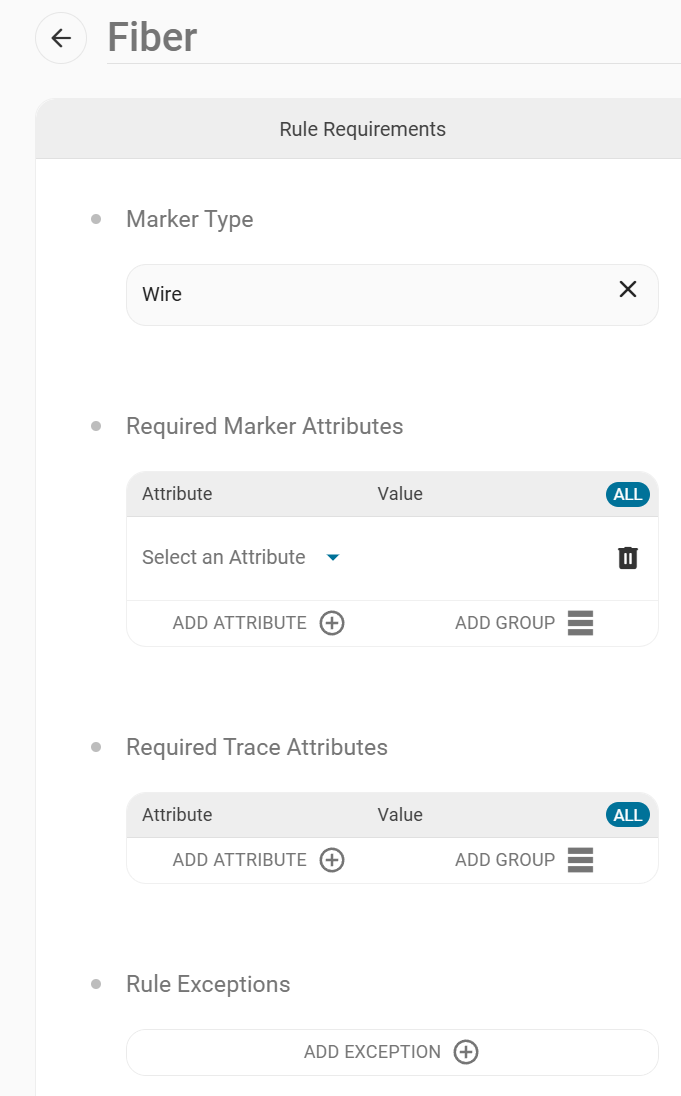
The Rule Requirements section contains the Marker Type and Required Marker Attributes or Required Trace Attributes. Here we see the Marker Type is set to "Wire." If we want this to apply to a Fiber Com, then we need to set this under the Required Trace Attributes.

By clicking "ADD ATTRIBUTE +," we can search for the Cable Type attribute. Under the "Value" column, a picklist with Cable Type values will pop up, and we'll choose the "Fiber" option.
*Helpful Reminder:
Marker Attributes - Attributes that exist on one particular marker in Photos. An example of this is diameter. If this value changes, it only affects that one, specific marker in your job.
Trace Attributes - Attributes that exist throughout a cable's trace. Examples of this are Cable Type and Company. If these are changed, the software will propagate the change throughout the job anywhere the cable is traced.

Under the Required Marker Attributes and Required Trace Attributes, clicking the "ALL" button, which applies "AND" logic to all attributes listed, allows you to toggle it to "ANY." This gives you the opportunity to set flexible "OR" logic for markers with attributes such as "grounded=true" or "proposed_ground=true."

The Rule Exceptions section is where you can add a description of an exception to the rule to help propagate understanding of niche or complicated specification and standards rules throughout your team. You'll enter a text string, explaining the exception, and then that text is shown on the marker when it's in violation so that users performing make ready engineering can determine if the violation can be ignored or not.
In the above example, the streetlight drip loop will have an exception if other markers are in violation with it, as seen below.

When you click on the "i" in the yellow circle on the left-hand marker, underneath the violations ("S/L drip loop must be: 12" away from catv," etc.), there is a section for '* Exceptions: S/L drip loop" and the exception(s) will show there.

Back under the "Rule Requirements" section of the Clearance Rules Details view, If the "Marker Type" is set to "Wire" or "Equipment," there will be a section to edit or add Pole Clearances.
The "X" will remove the value (for example, under "Direction," it'll remove the direction that's specified)
The Distance is in inches
Direction can be set to Below, Above, or From
"Clearance Rule" is what the rule should be applied to in the software
You can check the checkbox if you want to ignore existing violations to a certain item listed
Scrolling to the bottom will show the "ADD CLEARANCE +" option to add a make ready clearance. A row
will be added to the bottom where you can fill in the distance, direction, and clearance rule, as well as mark if the existing violations should be ignored.

Midspan Clearances set the clearance rules for the midspan. In the above example, it shows that the Fiber needs to be 30 inches below an open secondary in the midspan, and this rule needs to be applied in both proposed and existing conditions. This Midspan Clearances section can be toggled on or off.
*Note - For Midspan Clearances, you can set distances between wires, and you can set distances that wires need to be over certain types of midspans. For the above example, the Fiber needs to be 186in Above the Sidewalk.
Some helpful tips for using the Clearance Rules in the Model Editor would be to remember that order matters within your Make Ready Clearance rules. For example, a more specific kind of wire or equipment will need to be placed above a less specific wire or equipment of the same type. For example, if you have a rule for a street light and a rule for a grounded street light, the "grounded" version will have that extra attribute, making it more specific, so that ruleset will need to be placed above the non-grounded ruleset.

You can move rulesets using the "Edit Clearance Rule Order" button, which gives each ruleset a 6-dot handle that you can use to click, drag, and drop rules in the order you want them to appear. Then you can "Save Clearance Rule Order" in the top right corner of the screen or choose to "Cancel."
Proposed Cable Logic
Your market may require complex logic for inserting proposed cables, using several rules for placing them. Custom proposed cable logic modules are available for making inserting proposed cables simple and determining make ready calls more quickly, simply, and effectively. Reach out to our support team if you want to take advantage of this feature.

Under "Proposed Cable Logic" is where you can choose between the "Basic" logic (which is the default for the software), or the cable logic modules that are custom made for you. You may also select which Photo Routine (that include a single wire) should run when you insert the proposed. The Proposed Cable Option available lets you turn on or off whether the height of the proposed cable in the midspan should be adjusted if its traced cable on the pole is adjusted. Make sure to "Save" any changes.
Virtual Rideout
Virtual Rideout is a presentation tool that filters down data to the necessary information, allows you to collaborate on designs, and makes presenting Make Ready calls easy. It can be accessed via the App Tray. You can read more about it in our Virtual Rideout Manual.

Here in the Model Editor, you can set up filters using the Logic Editor to specify which poles should be included in the Virtual Rideout.
Pole Loading
Here is where you can configure different aspects of pole loading for Integrated Pole Loading or Parallel Pole Loading Exports. The Attributes, Tools, and Photo Inputs here work the same way as the Attributes, Tools, and Photo Inputs previously discussed; these are just filtered Attributes, Tools, and Photo Inputs that are relevant to pole loading.
Default Settings
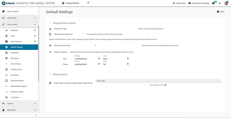
The Default Settings is where you can set the default soil type, include any wind angular resolution, enter standard load case(s) to add to all poles, and add any cable types that should be exported as Messengers Usage Group for SPIDACalc exports.
Pole Specs

The options in the dropdown for Pole Specs comes from the pole_spec attribute. If you need other options for Pole Spec, you'll need to edit the "Pole Spec" attribute's picklist. This picklist should be populated by your client file.
Once you select a pole spec, you can specify which pole spec from the "Pole Spec" attribute it pertains to and modify the material properties of the pole, such as the buried depth of that pole spec, the circumference 6 feet from the butt of the pole, the pole top circumference, the material strength, and the modulus of elasticity.

If you are creating a pole spec for a steel pole, you will additionally enter details for the tip load, wall thickness, and weight.

For creating a pole spec for a concrete pole, (whether reinforced or prestressed,) it has all the same inputs as a steel pole with the addition of the minimum moment capacity (in pound-foot units).
Wire Specs

Moving along to Wire Specs, this is where things can get a little more complex. (The wire specs in the drop down are based on the wire_spec or "Wire Spec" attribute. If you need more wire specs, you'll have to edit the "Wire Spec" attribute.) Here in Wire Specs, you can choose the weight of the wire, edit the tension tables, enter the diameter, modify the cross sectional area, specify the modulus of elasticity, and change the expansion coefficient.

With the tension tables, for slack tension and full tension, you can manually enter the tension table values or you can choose to calculate tensions from the baseline, which you will need to fill out. Under "Tension Table Calculations" is where you will select the option to either manually enter tension table values or calculate tensions from the baseline.
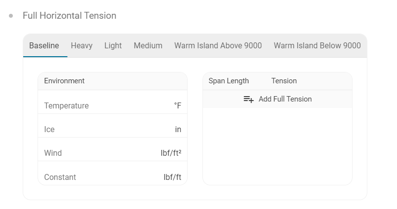
The tension table headers (Baseline, Heavy, Light, Medium, Warm Island Above 9000 ft, Warm Island Below 9000 ft) are the NESC loading districts. Again, these can be entered manually or calculated from the baseline. If you want to calculate these loading districts from the baseline, you'll first have to enter the Environment details (the temperature in Fahrenheit, inches of ice, pound-force per square foot of wind, and the constant pound-force per foot of wire). Then you'll need to enter how many pounds of tension are applied to the wire for a specified length of the span. Once these details are entered in the Baseline, the rest of the NESC districts can be calculated from it.

Bundled cables will need to be properly modeled for tensions calculated from a baseline messenger tension. Bundled cables should list their total weight and diameter in the top level inputs for the wire spec, and list the weight and diameter of each individual component under this Bundled Components section.
Anchor Specs

With Anchor Specs, the option drop down is based on the anchor_spec or "Anchor Spec" attribute. This is where you'll edit the rod strength. Under "Strength Type," you can choose "Rod and Soil Holding Strengths" where you'd specify the holding strength of the rod alone and then the holding strength of different soil types. With "Combined Holding Strength," you can specify the holding strength of both the rod and the soil, but this will not account for the different classes of soil.
Insulator Specs

For Insulator Specs, here you can specify a lot of the dimensions of an insulator that'll affect the load based on how the wind hits it. The Insulator Spec is a drop down based on the insulator_spec or "Insulator Spec" attribute. The aspects of an insulator that you can change here are the pole side area, the lateral area, the vertical offset (the vertical distance between the bolt measurement and the point that the wire is attached to on the insulator), and the weight. The pole side area and lateral area are illustrated in the below image.

The pole side area is outline in orange while the lateral area is outlined in gray.
Arm Specs

Like everything else, the Arm Spec drop down is based on the arm_spec or "Arm Spec" attribute. Here you can specify the width of the arm, the height of the arm, the depth of the arm, its weight, and its offset.
Equipment Specs

Equipment Specs are based on the equipment_type or "Equipment Type" attribute combined with its corresponding spec. For example, if the Equipment Type was "street_light_bracket," the Equipment Spec drop down would be based on the street_light_spec or "Street Light Spec" attribute.
Depending on the equipment type, you can modify the weight, length, rise, height, width, depth, shape factor, or horizontal offset. The shape factor is a number that determines the type of shape the equipment is and how that affects the way wind hits it. If it's round, the shape factor is 1. If it's square, the shape factor is 1.6. A round lattice shape gets a shape factor of 2, while a square lattice shape gets a shape factor of 3.2. The horizontal offset is the distance of the center of gravity of the equipment from where it is bolted on the pole in the horizontal plane.
Sidewalk Brace Specs

The Sidewalk Brace Specs is fairly simple and straightforward. This is based on the sidewalk_brace_spec or "Sidewalk Brace Spec" attribute. This is where you can change the length (in inches) of the sidewalk brace.
Pushbrace Specs

Pushbrace Specs are based on the pushbrace_spec or "Pushbrace Spec" attribute. For the particular spec, you'll enter the diameter, cross sectional area, modulus of elasticity, and rated breaking strength.
Load Cases

Finally, we've reached Load Cases. Here you can specify a load case to be used for pole loading. Load Cases are based on the NESC, so you'll want to get out your 2023 National Electrical Safety Code (NESC) to inform you on which values to use. The district is based on NESC districts.

You can get more specific in your Environment Parameters as to the temperature in Fahrenheit, the horizontal wind pressure in pound-force per square foot, the radial ice thickness in inches (how much the ice adds to the radius of the cable), and ice density in pound per cubic foot. You'll want to refer to Rule 250 of the 2023 NESC to determine the values to enter for these parameters.

For Load Factors, there's conductor constant factor, guying factor, longitudinal deadend loads, general deadend loads, transverse wind loads, transverse wire loads, and vertical loads. When entering values for these load factors, refer to Rule 250, 251, 252, and 253 in the NESC.

Strength Factors include Fiber Reinforced Polymer, Foundation, Guy Anchors, Guy Wire, Metal, Prestressed Concrete, Reinforced Concrete, Support Hardware, and Wood. Refer to Rule 260, 261, 263, and 264 for inputting the values for these Strength Factors.
Exports
Photo Form Editor

The Photo Form Editor is a custom deliverable photo of the pole. Here, you can set custom colors, add or remove attributes, and upload a company logo to the photo deliverable. You can also have multiple Photo Form templates so that each market can have its own form.
To start, either search for an existing Photo Form to edit, or create a new one by clicking on the blue "+" icon.
The software will open an example photo of a pole so that you can see how your changes will look. In the options bar towards the left, you can use this to format the Photo Form.
Under "General Options," you'll find the page orientation and font size options.
Under "Measured Heights," you'll find options to change the look and feel of the measured heights on the photo.
Under "Page Info," you can edit the information that will appear in the top left corner of the Photo Form. Here you can add attributes, remove attributes, and reorder them accordingly.
Under "Attribute Info" (which is the text box shown in the bottom right-hand corner of the Photo Form), you can add, remove, and reorder attributes as well.
The "Logo" section is where you can select your company logo (which can be uploaded under the Files section of the Model Editor).
You can find your newly created Photo Form template in the Download Manager on the Maps page under "PHOTOS" and "Photo Form PDF." Under "Node Types to Export" and "Additional Photo Types to Export" you can find the Photo Form Template input and select your Photo Form from the dropdown.
Map Print Templates
Here is where you'll see all your Map Print templates listed. By clicking on a template, you can rename it, duplicate it, or delete it. For more details on creating Map Prints, check out our Saved Views and Map Prints Manual.
Saved View Templates
Similar to Map Print Templates, this section will show a list of your Saved View Templates with options of what to do with them. See our Saved Views and Map Prints Manual to learn how you can manipulate the look and feel of the map, save those changes, and use them in Map Prints. With your Saved View Templates listed here in the Model Editor, you can rename your Saved View Template, duplicate it, or delete it.
Map Styles
Underneath Map Styles, you'll be able to find the sections for Custom Icons and Custom Line Styles.
Custom Icons

Uploading an SVG file for your own custom icons means more options for customizing the look and feel of your project. Underneath "Map Styles," you’ll find the “Custom Icons” section. To add a new icon, click the blue plus button, and enter a name for the icon. After clicking the “Continue” prompt, you’ll have the option to upload an SVG file.
*Make sure this file is under 3KB and is a valid SVG file. If you want control over changing the color of the icon, ensure that the icon has no fill.
Click “Choose File” to navigate to and open your custom icon’s SVG file. After uploading the icon, you can add it to your personalized Icon Collection. (The Icon Collection is a way for you to organize your custom SVG icons and search them more easily later.) If you don’t already have any icon collections, you can click on “EDIT ICON COLLECTIONS” seen on the dropdown. You’ll then create a name for the collection and click on the blue plus button to add it. Once you’re done adding the Icon Collection(s), you can click on “Close.” If you don’t want to leverage the Icon Collections, you can click “Skip” to skip this step.
To finish creating the custom icon, click “Finish Creating Custom Icon.” You’ll get a message letting you know that your icon successfully saved.
If you need to delete a custom icon, find it in the Model Editor and click on "Delete" in the top right corner. Now you can view your new icon on the Maps page!
Go to the Map Styles, click on the style's icon to edit, and find your custom icon in the Custom Icons section towards the bottom. More on Map Styles in our Map Styles Manual.
Custom Line Styles

The Custom Line Styles feature can be found in the Model Editor under ‘Map Styles.’ Here you can add a new custom line style by first clicking on the blue plus button and naming the line style.
You can then choose components of the line (a line or a space), specify the length, and make custom combinations of these components to create a custom line style for selection in the Map Styles Editor. In the above example, the line will be created with a dash of length '10' followed by a space of '5' followed by a dash of '10' followed by a space of '5,' and the pattern is repeated.
Finish your custom line style by clicking “Finish Creating Custom Line Style.” Now your custom line style can be used.
If you go to Maps, you'll be able to see your Custom Lines as an option in the Map Styles! More on Map Styles in our Map Styles Manual.
Mobile
Underneath the Mobile section of the Model Editor is the "Mobile Options" and the "Mobile Assessments" sections.
Mobile Options

Currently there are two options for accessing jobs via mobile devices with this job model: Hover Attributes and Mobile Assessments Workflow.
Hover Attributes allows you to specify which attributes should display in a popup when fielders hover over an item (i.e. node, connection, or section) on the map. The Label option, when checked, will add the name of the attribute (i.e. Note) followed by a colon and space(: ) with the value of the attribute following. If the label option is left unchecked, then only the value of the attribute will be displayed in the popup.
The "Separator" field above the table of hover attributes is where you can type in any character(s) that should be used to separate the attribute(s) that are displayed when the fielder hovers over an item. For example, you might type a comma followed by a space so that any attributes displayed will be displayed as a comma separated list. Or you can use " | " to separate the attributes with vertical lines.
Mobile Assessments

The next section of the Model Editor is Mobile Assessments. Mobile Assessments allows you to create custom field tools for your team to enter information from the field in a guided, step-by-step fashion. You can check out our Mobile Assessments User Manual for more information.
First, you’ll name your assessment and choose the icon and color for its Tool button. After selecting the proper permissions you’d like this assessment to follow, start adding Assessment Steps.

Fill in the various options for the step by expanding the Step row, and then choose the Step Action. You can reorder and adjust Steps and Step Actions as needed.

Once you are finished with your Assessment Steps, click “CONTINUE” to enter you Assessment Actions which determine what happens when you use the Assessment to create a new node, assess an existing node, or complete an Assessment. You can also choose which Toolset your Assessment can be found under.
Reference Layers
The Reference Layers section allows you to create a map layer from large, static datasets, accessible in any job open in the Maps page that uses the job model that the reference layer is uploaded to.
To create a new reference layer, open up the job model in the Model Editor, then click the blue plus ("+") button. This will prompt you to name the new reference layer. Then you'll configure the following settings:
Upload a Shapefile or CSV
Shapefiles must include all .shp, .dbf, and .prj files containing point geometry (can be zipped or unzipped)
CSV files must have "latitude" and "longitude" columns with valid EPSG:4326 coordinates
Choose the layer's visibility from the Layer Type selections
Model (Public): The layer will be visible to any company that has read access to the job model
Model (Private): Only companies selected in the dropdown provided with this option (see screenshot below) will have visibility on this layer

Company: Only users in your company can see this layer on any job
Always Show Layer: This option, when checked, will ensure the layer always appears in the Imported Layers (see below screenshot for reference of where the layer will appear); this way the reference layer does not need to be manually loaded onto the job

Declare the feature type
Select whether you're uploading a file with point data or line data
Make sure your file only contains data for one type of feature (all points or all lines)
Map the layer properties to Katapult Pro attributes
Properties from the file you uploaded will show up on the left, and the attributes they're mapped to in Katapult Pro are on the right
You can rename the property in the Katapult Pro platform to your choosing
Choose an attribute that has a different value for each data point as a unique key (optional)
This unique key will be used to index the data points (which may be used in searches later)
Configure styling for your points or lines with Map Styles based on their attributes
To learn more details on how to modify Map Styles, check out our Map Style Manual
Advanced settings allows you to determine the zoom level at which an area of location data will be rendered (optional)
“Max Visible Radius” is the largest radius in which the reference layer will be visible (in meters)
“Minimum Zoom Level” refers to the most zoomed out you can be to see the reference layer, with 0 being zoomed out all the way and about 30 being zoomed in all the way
“Rendering Order,” is the order in which reference layers are rendered
If a reference layer has an order of 1, it will be loaded first, with any following layers being loaded on top of it
If two or more layers happen to have the same rendering order, they will be rendered in the order of when they were uploaded such that the most newly uploaded layer will render last and appear on top
Upload your reference layer
The larger the layer you're uploading, the longer the process will take
Do not navigate away from the window until the upload is complete, or else you will lose the upload
A progress bar will show you how far along in the loading process you are, and a "Saved Successfully" message will appear on your screen when the layer is successfully uploaded and saved
If you did not check the "Always Show Layer" option under the "Layer Type" step, you will have to load the reference layer onto the job manually.

From the Map page in an opened job, click on the Map Layers. Expand “Imported Layers” to click “Manage Layers…” and open a dialog. From here you’ll be able to choose the reference layer(s) you want to see on your job.
API Layers
The API Layers section allows you to create a layer from an API endpoint, accessible in any job using any job model in the Map. (If you have more than one job model, then this section will only show up on your default job model. Although it may only appear in your default job model, API Layers created here are accessible by all other job models.)

Here is a map layer in ArcGIS. The only thing you'll need from here is the API endpoint address.

In Katapult Pro, go to the Model Editor and click on the API Layers section found underneath the Reference Layers. To add a new API Layer, click the blue "+" button next to the search bar.

This Untitled API Layer page will appear. You can rename the layer by clicking on the "Untitled API Layer" placeholder text and start typing the new name. Under "API Endpoint URL," enter the endpoint URL. You can then fill out the layer name, group, etc. (the next step appears once the current one is completed). Or you can click "Auto-fill Layer Details." Click this to automatically fill out layer details based on information shared by the API Endpoint. (If you completed filling out information for each step, clicking this button will overwrite all of that information that was already entered.)

In the above example, clicking "Auto-fill Layer Details" filled out the layer name but paused at Layer Group. Choose a layer group from the dropdown to add this layer to or press "Skip." If there are no listed groups, you can create a new one by clicking "Manage Layer Groups," entering a name in the "New Layer Group" input and click the "+" button. (This is also where you can later delete layer groups.) After managing this step manually, the software resumes automatically filling out the layer information.
Once this process has finished, make sure all the information is filled out. For Layer Styles, you can check the box next to "Use Sources Styles" for the API Layer's style in Katapult Pro to match its style in its source. If this is checked, the source style will be fetched from the API Endpoint on page load and used instead of any custom style specified in this "Layer Styles" section.

On the Maps page, you can turn on the API Layer by clicking the Map Layers button in the bottom left corner, opening the "Imported Layers" option, click "Manage Layers...", and finding the layer (or its layer group) under the API Layers dropdown in the window that opens.
Adding API Layers In Bulk
If you have the API Endpoint for a server containing several map layers, you can use this URL to upload all the included layers at once.

To get started, click the blue "+" button. Enter the API URL endpoint, then click outside of the input area. If the endpoint is to a map server with multiple API layers, the software will recognize this and list all the layers it found stored at this API endpoint.
You may review the layers and optionally choose a Layer Group to add all of them to before creating the API Layers. Click "Create API Layers" to create all the layers with the name they are listed as with all their details automatically filled. If you would like, you can open the individual layer to edit its settings.
*While bulk adding API layers, keep in mind that you will have to delete API Layers individually.
Layer Groups
As shown earlier in this manual, open an API layer in the Model Editor to specify which Layer Group it belongs to, if it belongs to one. (You can also manage Layer Groups from this input.)

From the Maps page, you can import these API Layers into a job from the Map Layers button towards the bottom left corner. Similar to importing a single API Layer, you can import multiple API Layers into a job by importing a Layer Group. These imported layers will show up nested underneath their Layer Group. This makes it easy to select and deselect all the layers at once. If you want to select most of the layers, you can select the Layer Group at the top level then deselect the layers you don't need. If you only want to select some of the layers, you can open the Layer Group and make your individual selections.
Files
Next in line is the "Files" section of the Model Editor. Here you'll upload files to be used in the software in various places. For example, you can upload a logo here and use it for your Map Prints or Photo Form.

First you'll click the blue "+" icon to upload a file. Select your file and click "Open." Once it is uploaded, you can rename, copy, download, or delete the file.
Configurable QC
Create your own custom quality control modules to help you and your team tackle the toughest and most complicated projects.
In the Model Editor, find the Quality Control option on the left-hand side. Create a new Quality Control module by clicking the blue plus button and naming the Quality Control module.
Within this module, you can add warnings which, if triggered, will display a message of your choice. Type your message in the ‘Warning Text’ area. Click the dropdown arrow to specify the warning type (what part of a job the warning applies to), such as the job itself, nodes, connections, or sections.
Optionally, you can use the Logic Editor to add a filtering condition so that the warning is applied to specific jobs/nodes/connections/sections (depending on the entity you chose in the "Warning Type" step). If you’re using a data path, start at whichever entity you chose in the “Warning Type” section (job/node/connection/section).
Finally, create a “Warn Condition,” which uses the Logic Editor to set the parameters where the warning will apply to that entity (job/node/connection/section) specified in the “Warning Type” (and “Filter”) steps.

For example, you can create a warning that a pole is missing a SCID attribute. You may put “Pole is missing SCID attribute” in the “Warning Text” portion. For the “Warning Type” step, you’ll say it applies to “Nodes.”
For the “Filter” option, you’ll use the Logic Editor to say that this warning only applies to nodes with a node type of “pole.” So you'll use the Operator Type "Equal." We're checking if the node's attribute of node_type is equal to "pole," so the first argument will be the data path to the node's node_type, which is 'node.attributes.node_type.*'. Then the second argument will be the literal string "pole." So this statement reads "filter nodes (which we specified in the "Warning Type" step) where the node's attribute, 'node type,' is equal to 'pole.'"
Note: Notice the "Inputs" block abover our "Equal" expression block. "Inputs" allows you to select example data to see the way it's structured so you have visibility into how you'd want to write any data path or where the data you want to access may be, if it exists. In this case, we're able to select an example job and the SCID of a particular node. In the screenshot above, we can see 'node' at the top level, with 'attributes' underneath that.

If we scroll down to find 'node_type,' underneath that is an ID, so we'll need to use an asterisk (*) for a wild card, and then there's the value. Hence the data path 'node.attributes.node_type .*'.

In the “Warn Condition” step, you’ll write a condition statement using the Logic Editor that, when evaluated to "TRUE," triggers the QC Module. So in this example, we'll write a condition statement that says if the SCID attribute does not exist on the node, give the warning. So here we'll use the Expression block with an Operator Type of "Does Not Exist," and then the first argument will be the data path to the SCID attribute, 'node.attributes.scid.*'. So this is essentially saying that if it's TRUE that the SCID attribute Does Not Exist, trigger the warning. Then you’ll click the “Finish Creating Quality Control” button.

Once you have your QC modules built, you can create your own tool to run these modules. You can go to the Tools section of this manual for instruction on how to create it. Make sure you use the 'Run QC Modules' option under the "Tool Action" step.

You can then click the tool to run the quality control module, and the ‘Quality Control Results’ will pop up in a window (shown in the screenshot above). In this case, the warning message is displayed for each pole; you can navigate to the pole by clicking on the magnifying glass icon to make corrections.
Model Options

Set defaults for a job model in the Model Editor under “Model Options.” Here, you can set the default Map Style for your job model so that any job created with this job model will use that Map Style when it's created. You can also set defaults for Map Labels, rounding mechanics for Map Labels, Mobile Map Labels, and Photo Labels.

The Node Counter Logic is a configurable default to change what nodes should be in the counter on the Maps page. Typically, on the desktop, this "Completed" counter checks for poles that have a checked "Done" attribute and keeps a running tally of them. If you wanted to change the logic for this, Node Counter Logic is the place to do that. If you want to revert back to the default counter logic, simply delete the Logic you created using the Logic Editor and save your changes.

The "Only Allow Admins To Edit This Model" will prevent any user who is not an admin from editing the job model when it is turned on, even if the user has "Model Editor Write Permission." Underneath this is a setting for selecting a time zone for the model.

Continuing down the Model Editor, you can configure the Address Tool to use custom attributes. You'll find a table for mapping the default attribute used to a custom attribute you would select from the dropdown. If the "Write Data to Both Attributes" toggle is turned on, the address tool will use both the default attribute and the custom attribute for saving address data.

"Allow Public Feedback on Jobs With This Model" lets anyone inside or outside your company leave feedback on jobs that are built on this job model when it is toggled on. That feedback is then visible to everyone.

As you'll see in the screenshot above, this is also where you'll have access to delete the job model. Exercise caution when deleting job models, as this action cannot be undone. Note that jobs using the job model you delete will be affected and must have a new model assigned to them.
There are other model defaults that aren't yet accessible in the Model Editor but can be configured by us. Certain features require a specific attribute to be present (i.e. many of our exports look for nodes that are "poles" and export those nodes' data), and these 'other model defaults' allow you to change the required attribute to a custom attribute or picklist option. For example, the default ordering attribute is "scid." This is used by exports to order poles. You can change this to something like "pole_id" so that your poles are ordered by their Pole ID and will show up in exports.
Another example is the default pole node types, which is "pole." Exports look for this node_type, "pole," to include those nodes in the export. The search bar on the Maps page will also use the node_type default as the initial search filter. This default could be changed to something else; if your market is different and revolves around a different type of node, like if you're doing underground work and deal mostly with handholes, you can change the pole node type to "handholes."
Reach out to support@katapultengineering.com with any questions or if you'd like to configure these model defaults.
Model Sharing
Share your model with another company on a different server with the Model Sharing feature. This is an experimental feature that will need to be enabled by your company admin.

Your company admin will need to navigate to the Project Management page, click on "Company Options" underneath the Admin section, and turn on the toggle for Cross-Server Model Sharing so it appears blue.
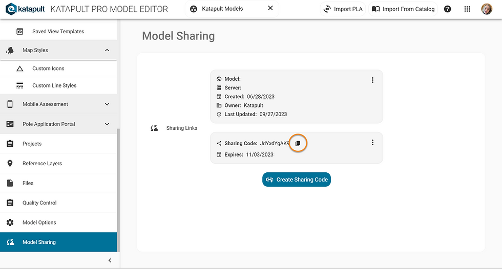
Back in the Model Editor under "Model Sharing," click on the blue "Create Sharing Code" button to generate a Sharing Code. This will generate a code you can copy to your clipboard (by clicking the button circled in orange) to share with another company.

The company receiving the model will use that Sharing Code when they create a model. They'll click on "Add a Shared Model," enter the code, and click "Continue."

The "Shared Model Details" will pop up. Clicking on the three dot menu in the top right allows you to set an alias for the model, a description, or delete the model. Now this model will appear when you go to create a new job in the Maps page.
*Only the company who owns the model will be able to edit the model.

If something within the model does change after the model has been shared, a warning will be displayed inside the Model Editor.

If the owner who created and edited the shared model clicks on the Model Sharing option in the Model Editor, they can update the shared model for the other company.
Recent Updates
We've included the two concrete options for pole material for a pole spec in mid-May this year. More recent updates to the Model Editor also include the steel option for pole material, API Layers, Attribute Sets, Photo Inputs, more options under Pole Loading, Custom Line Styles and Custom Icons, Configurable QC, Model Options, and Model Sharing. The Proposed Cable Logic section was released a couple years ago, and we added a section for Pole Loading.
Thanks for reading! If you have any questions about the Model Editor, contact us at support@katapultengineering.com. How can we improve our documentation? Let us know in the comments below!


Comments