%20small.png)
Katapult Pro Annotations, Tracing, & Hardware Details Manual
- Zachary Carlson
- Apr 9, 2021
- 23 min read
Updated: Oct 21, 2025

Content Links
Cable Tracing View
Annotations are used to mark up the heights of attachments on poles, and Tracing is how we carry their connections throughout the job. We do both steps at once using the "Cable Tracing View."

To turn this on, click on the “Cable Trace View” button at the top of the Map page after opening Katapult Pro in Chrome. When the view is on, the button icon will turn blue, and there will be a highlight behind the connections on the map.
Now you are able to click on the connections (not the nodes or sections) to open up Cable Trace View in Katapult Pro Photos. Start at the first connection at one end of the job.

Clicking on this reference span (the pink span with the orange arrow pointing to it) will open Photos in a new tab. Here you will see a multi-panel view. In the above case, a midspan and pole would be displayed.
*Having dual monitors is helpful because you don’t need to keep switching between the Photos tab and the Map tab.

If you need to switch the order of the photos in this view, you can click on the “Swap Photos” button located at the top middle of the page. Choose a photo order that makes sense to you and simplifies the annotation and tracing process.
Placing Markers

At this first span, start on the pole photo, and open the One-Click Menu by left-clicking on the photo, which places a temporary input marker. Then, if you have the option, click on the black icon (we call this the Photo Toolset Chooser) and make sure you are using the Measure picklist (or the Measure Photo Toolset).
*Not all clients will have the Photo Toolset Chooser—for some users the attachment options are contained in the same list as the Classification list. Also, some clients will have their Measure Photo Toolset labeled as the PLA software they use.
Once you have your Photo Toolset selected, you will see a list with different assemblies, equipment, and wires. Some of them might also have a letter or number in parenthesis to show the keyboard shortcut associated with the option.

*This Photo Toolset list can be configured in the Model Editor and customized specifically for you. You can set up routines of commonly used builds, equipment, and wires, and can set up desired shortcuts. If you have any questions, please reach out to support@katapultengineering.com.
Start at the top of the pole and work your way down when annotating attachments.
To add a marker, select the correct or closest option from the dropdown. You can filter out the options in the picklist by typing in the search bar.

Once you find the correct option, click it. If it is a routine, the software will run you through the entire routine. For example, if the "Ridge Pin & 2 On Arm (2)" was selected, the top ridge pin would be placed first, and the next click on the photo would place the 8' arm with 2 pins nested in it. (The 2 in parentheses tells us that we could hit '2' on the keyboard instead of left-clicking to open the One-Click Menu to run through this routine.)

When you place a marker on the photo, you want to make sure you click where the bolt goes through the pole face you are measuring for consistency. Be sure to account for parallax that occurs; if the bolt is not on the front-facing side of the pole, it may mean that the bolt hole is slightly above or below the bolt, depending on what side of the pole it's on.
Now that the markers are placed, you can move them by clicking on the handle of the marker (not the circle). Simply left-click and hold, then move the marker to where you need it and release the click.
Entering Marker + Trace Details
If you right-click on a marker, it will open up the details window for that marker. When items are nested, right click on the item you need to edit. For example, in the above GIF, you could right-click on the brownish 8’ arm marker to edit the spec of the arm. If you want to edit the insulator, you should right-click on the greenish portion of the handle. Lastly, if you have to make edits to the wire, right-click on the bluish purple marker.

For wires, you will have two tab options: Marker and Trace. Marker attributes pertain to any data that should exist only on that specific marker where the attachment is located in the picture. Trace attributes will contain any data that should be updated throughout the wires' trace in the job and will be shared across multiple markers (such as the Company, Cable Type, etc.).

Under the trace tab, you will find Cable Type and Company attributes. You can change the cable type at any time by clicking in the textbox and searching for the appropriate option from the picklists. You are able to do the same thing with "Company." Look through the picklist to find the correct company.
*If you do not see an option needed from your picklist, go to the Model Editor to add the option. Please refer to the Model Editor Manual for more instruction.
For the Utility company, you may want to check the box to set it as the default. This will allow you to quickly place utility wires and equipment. With the default box checked, the company name will autofill.

Up at the top of the wire menu towards the right will be 4 symbols. Clicking the carrot arrow will collapse or expand the wire menu. The stacked boxes with an arrow pointing from one to the other will remove the item from where it is nested, popping it out of the annotation(s) it's inside. The three-dot menu is discussed in further detail in Marker + Trace More Options, and the trash can button is discussed in further detail in Delete Markers.
Nested Markers

You can remove a wire from an insulator, and you can also remove an insulator with a nested wire from an arm. So make sure you are at the correct item when you click the button to 'pop out' that item.
The wire or 'insulator and wire' bundle will be placed at the same height when the button is clicked. (See GIF above.) If you need to nest a wire or bundle into an arm, just left-click and hold on the bundle you want to move into the arm. Make sure the cursor is over the marker you want to add to, and once you see the “Drop to Add” text, you can release the click. Again, you are going off the cursor position, not the circle that marks the height of attachment.

*You cannot nest the wire into an insulator that's inside an arm like the above picture. (The wire will end up being nested inside the arm, not the insulator.) First remove the insulator from the arm, then drag the wire to add it to the insulator, then drag that 'insulator and wire' bundle to the arm to add it correctly. If you need to nest a wire into an insulator inside an arm, you would first need to remove the insulator (greenish handle) from the arm (brown colored handle), add the wire (blue and purplish handle) to the insulator, then add that 'insulator and wire' bundle to the arm.
Marker + Trace More Options

Moving along the wire's menu at the top, clicking the Three Dot Menu will open more options. Under the Marker tab, you will be able to add or remove attributes if needed.

The available options under the Trace tab deal with the trace of the wire. Clicking the "Proposed" option that's listed first will mark the wire as 'proposed.' Doing this will add a proposed checkbox to the wire. You can click on the checkbox to unmark the wire as 'proposed.'
Under these options, you can also add a marker to a trace, remove a marker from the trace, split the trace of the wire (used when wires are incorrectly traced in a job, discussed more in the Helpful Tips section of this manual), and delete the trace.
Delete Markers

The last button in the top right of the marker's menu is the trash can icon or delete button. This will delete the marker and anything nested in the marker as well.
Power Space

Once the top assembly is marked up, keep moving down the pole. Look for any equipment or other attachers you need to mark. In the above image, the next wire is a neutral at 30'-6". You can click on the photo to place a temporary input marker, then search for a neutral option.
*The picklist will come from the pole loading analysis platform you are using. If you are not doing PLA, you will be able to use a “wire” marker and select the cable type after the wire is placed. You will not need an insulator.

Because you set the Power company as the default, you will not need to go into the trace options of the wire to enter the company. If you need to change anything, you can right-click on the insulator or wire to open its details.
Continue moving down the pole, marking all attachments and equipment.
Photo Chooser

If you need to, you can click on the “Photo Chooser” button at the bottom left of the photo to see all reference photos for that pole location. Use these photos to identify communication owners, check for equipment, and see other angles of the pole.
If your field crews did take multiple pole height shots, you can also set which one is best and should be used as the main photo by clicking the star icon at the top right of the photo. To exit the Photo Chooser view, click the gray space on the photo. This will take you back to your main photo for trace view.
Communication Space

When you get to the communication space, find your 'wire' option. For those who don’t have PLA or don’t have communication bundles, it will only be “wire," while for those who have bundles, find the "insulator, messenger, and wire" option so that you can build the communication bundles properly.
Again, click on where the bolt goes through the pole while accounting for parallax. Once you click the wire option, the software will automatically go into the trace routine (it will want you to trace that wire to where it is at the midspan).

You will know you're in the software's trace routine when you see the notification in the bottom left corner of the screen that says "Click on the makers to connect."
*If you are just starting out, hit the Escape ("Esc") key on the keyboard to cancel out the trace routine.
Then you can fill in the Cable Type and Company. If you can’t identify the company yet, you can list them as “Unknown” until you are able to find a comm ID photo.

Because the wires are traced through the job, anything you update or change in the trace tab of one wire will propagate throughout the entire trace. So once you update the Company name at a single location, the company will update throughout the rest of the markers that were traced together.

If communication wires are boxed and run through the same span, include both attachments. In the above example one is a fiber optic cable, and the other is a telco attachment. The wires are placed at the same height of 23'-2”.
Copying + Pasting Markers

If you have multiple wires from the same company, you can use a copy and paste shortcut so that you don’t need to click on the photo and add a wire and its details for each one.
To copy a marker, left-click on the wire, equipment, or bundle you want to copy (you should see a yellow highlight around the item), then hit "Ctrl + C" on the keyboard. This will copy the marker, and you will see a notification pop up at the bottom left (boxed in orange in the above image), letting you know you successfully copied the marker.
Now left-click on the photo again to remove the yellow border around the marker. You can now hover your mouse cursor over the photo where you need to paste the marker. You do not need to click the mouse again. If you press "Ctrl + V" on the keyboard, the marker will be pasted at the height of the cursor.

*You can use the copy and paste shortcut even if the wires, bundles, or equipment are not exactly the same. Often, copying then changing some details (i.e. a spec or a company) is quicker then clicking, adding a new marker, and filling out all its details.
Once the pole is all marked up, you can now start tracing the wires across to the midspan(s).
Tracing Cables

You will have two options for tracing the wires to the midspan. You can do one wire or bundle at a time by hitting “~” on the keyboard (to the left of the "1" key). Or you can hit "Alt + ~” to initiate a trace routine (which we call the Extraction Loop) that will start at the top of the pole and work down automatically.
If you press only “~,” you will see that notification at the bottom left of the screen to “Click on the markers to connect.” You will now be able to click a marker on the pole (make sure to click the outermost portion of the handle if you are clicking on a bundle).

Once you have your marker selected, you will see a yellow border around the marker. You can now move your mouse cursor to the midspan photo and zoom in on that wire in the midspan. When the tip of the cursor is placed correctly, left-click to place the wire.
*As soon as you start the trace, a quick left-click will place the wire, so be intentional about where you click. You can always left-click and hold to move the photo around, but a quick left-click will place the marker. Also, make use of the wheel on your mouse to zoom in on the photo to accurately place the wire.

Now that the wire is placed, the trace action will end. You can see how the wire is traced because a yellow border will be around the wire in the midspan, and a yellow rectangle will appear to the left of the nested neutral on the pole. (If it wasn't nested in an insulator, it would be highlighted in a yellow border as well.)
If you change anything in the trace tab of the marker, it will update throughout the entire trace. You can also delete the marker in the midspan if needed; this is especially helpful if you accidentally traced the wrong wire.
Repeat this process until all appropriate wires have been traced to the midspan.
*This method is good for one off wires or for taps coming off a pole line, but generally you should use the trace routine, or Extraction Loop.
Extraction Loop

Hitting "Alt + ~" will commence the Extraction Loop. (Use "option + ~" if you are using a Mac.) The Extraction Loop will start at the top marker and work down. You will know you are in the routine if you see the notification pop up at the bottom left of the screen that says "In extraction loop. Press Esc to go onto the next item," which you can do if you don't need to trace the wire to that midspan.

As you click to place the wire in the midspan, the routine will automatically go to the next marker in the photo based off of height. So again, make sure you only left-click on the midspan photo to place the correct marker. If you need to move the photo around to have a better field of view, long click and move the photo, then release the click once the photo is in a good position.

When you get to the communication space, as you place markers in the midspan, you can use the diameter arrows to set the diameter of the wire. You will see a green rectangle fill in the wire as you adjust. The adjustments will be made in 0.25” increments, but you can click in the text line to manually enter a number.
*Diameters are typically only needed for PLA workflows when you plan on using the Com Wire Spec tool to enter wire specs. The Com Wire Spec tool uses these diameters to match up the wire to the appropriate wire spec found in our catalog. If you are using a different catalog or client file than our Basic Integrated Pole Loading, reach out to support@katapultengineering.com so that we can configure the tool to work with your catalog or client file.
When you get to wires that are boxed, the software will first go to the marker handle that is higher up on the photo (even if they are at the same height). So just make sure you are aware of which marker the software has selected (which one is highlighted) when tracing to the midspan.
To skip a marker that's not in the midspan but is highlighted on the pole, click escape (Esc) on your keyboard.
When you get done with the last marker, the Extraction Loop will end automatically. You can now reposition wires if needed or right-click on a wire to add data or attributes.

Once the pole and midspan are set, keep the Photos page tab open, but return to the Map page and click on the next connection. In the above photo, this will be the first aerial connection. Clicking the connection will open up that span’s photos; in the above instance, this is the pole-midspan-midspan-pole photos.

Now, because the one pole is already done, you can use the Extraction Loop routine to trace the wires to the midspan(s) and to the next pole.
Again, use the "Alt + ~" shortcut to start the Extraction Loop (or "option + ~" on Mac). Now you will need to click on the first midspan, then the next midspan, and finally the location the marker should be at on the pole to completely trace the marker. Once that is done, the routine will go to the next marker to trace through.
Remember, whichever photo your cursor is over, that is the photo you are currently interacting with. You can zoom in and out of each photo independently.
When you get to the communication wires, because the diameter was already set, you do not need to set it again, but you can adjust the diameter if the wire size does change.

*It is helpful to position the photos in a way that makes marking the communication wires easier. Try framing the midspan(s) and next pole photo in a way where you are zoomed in enough to accurately place the wire but aren’t too far in that you need to keep zooming out or in for each wire.
Also, during this step, you should only be worried about tracing the wires to the next pole. Even if new attachments are on the next pole, you are only worried about placing the traced markers correctly on the pole. Once the Extraction Loop is finished, you can then go to the new pole and go from the top down to fix any specs or add equipment or additional wires if there are any.
*It is best to completely mark up this pole before moving on in the cable tracing process.
Adding The Proposed Wire
Now that each pole on the screen is completely marked up, you can add your proposed wire if this is new aerial build.

If you hit the “+” (or "=") key or click the scroll wheel of the mouse, the software will automatically place a proposed wire on the photos displayed. The placement will be based on the Proposed Cable Logic you have selected in the Proposed Cable Logic section (under the Make Ready header) of your Model Editor.
Once placed, you can right-click on one of the proposed markers to fill in the trace details (Cable Type and Company). Also, if doing a PLA workflow, enter the correct diameter for the proposed wire on its marker in the midspan.
If you need to include additional proposed cables (inserting more than one), you'll need to press the "alt" key and "+" or "alt" and click the mouse's scroll wheel.
*To quickly insert proposed overhead guys, use the "shift" and "+" shortcut.
Modeling Crossovers
Especially if you're leveraging our integrated pole loading engine, you'll want to implement the following guideline for modeling any crossovers that may appear in your job.
Any spans with cables that are not in the crossover should be designed as reference connections in Katapult Pro.
A node should be used to represent the crossover by setting its Node Type to "crossover." Make sure that the spans that are running from poles to the crossover are connected to the crossover.

Above you'll see the Node Type set to "crossover," and the green lines on the map are the aerial cables connecting to the red "X," or the crossover. When fielding the crossover, the height stick operator should stand directly beneath where the cables are bolted in the crossover.
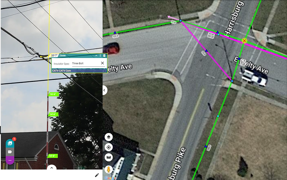
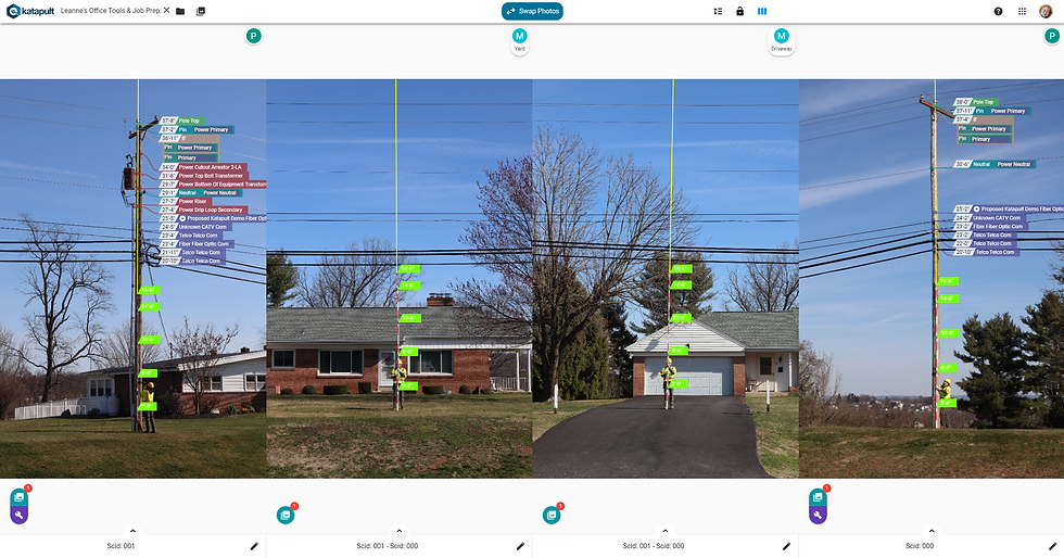
Notice that, in the image above, there is a photo that is pulled open to the left that shows a crossover. The angle at which this photo was taken allows the back office processor to see all cables intersecting at the crossover. As the field technician, ensure you are taking crossover shots at an angle that provides visibility to all cables intersecting at the crossover.
As a back office processor, make sure you're only annotating and tracing cables that are bolted in the crossover. Cables that are not bolted in the crossover will be traced in the reference span.

For cables that are in the crossover, you'll nest them inside a three bolt insulator. (Notice the partially annotated photo above shows one of the CATV communication cables going through the crossover on a three bolt insulator.) If cables are sharing a bolt, you can have them all in the same three bolt marker. For instance, if an aerial cable becomes an overhead guy, they can both be on a three bolt insulator.
Any overhead guys in a crossover should be marked as strands (change their Cable Type to strand). This will ensure loads are balanced properly during loading.
Hardware Details

Once you have traced all connections from a pole, marked equipment, and filled out the necessary details, that pole has been fully extracted. It is best to now run Hardware Details on that pole.
*Hardware Details is typically only run for PLA workflows, but sometimes is used to help link down guys. The Hardware Details button is the wrench icon, which is located under the Photo Chooser button at the bottom left of the pole photo, and it'll run hardware details on just that pole. It is also a tool in the Office Tools toolset on the Maps page that can be run on all the poles in the job.
When you click the Hardware Details button, return to the Map page and a window will now be displayed:

In this window, you can choose which details of the pole you want to enter. For PLA workflows, typically the only box left unchecked is the “Enter Power Cable Spec.” (The software has another quick tool for entering the power cable spec, which is covered in the Preparing Jobs For External Pole Loading Manual.)
*For non-PLA users, the only options that should be selected are “Link Downguys to Anchors” and “Skip Completed Items.”
Once the options are selected, click “Enter Hardware Details.”
If the pole has down guys, the routine will first prompt you to enter the height for the specified down guy.

If the pole contains multiple anchors, the software will highlight the current anchor and down guy that needs specified.

Back on Photos, you will see the above notification for selecting where the down guys are attaching to the pole. Click on the correct placement based on the down guy that is highlighted. (If the fielders entered down guys starting at the highest down guy and working to the lowest down guy, the down guy sizes will be listed from the highest down guy on the pole to the lowest down guy on the pole.) In the above image, the highest down guy (a 6.6M strand) is highlighted for placement.

If the down guy is backing a cable, you can click on the corresponding cable to have the cable's Company automatically copied into the down guy and for the down guy to be placed at the same height as the cable. You can always move the down guy marker after it is placed if needed.
You can manually place a down guy marker by clicking at its bolt on the pole and choose the corresponding Company as well.
If there are multiple down guys, work through each one, paying close attention to which anchor and down guy the software is asking you to link.

If you're only linking down guys to their anchors for Hardware Details, you can click on the anchor in the Maps page to open up the Node Info for the anchor. At the bottom will be a button to "Link Down Guys." This will take you through the same routine mentioned above.
If the pole has equipment, or you have a workflow where you need to set the direction of insulators and arms, the Hardware Details routine will also prompt you to set the bearing for these markers.

Again, the routine will start at the top of the pole and work down. When setting the bearing, you are looking for the direction that the insulator, arm, or equipment is facing. In the above photo, the cutout is facing the field side, so the dropper is placed to show what direction it is facing.
When setting bearings, the distance of the yellow line does not matter; you are only concerned with the direction. You can be really precise and manually enter the bearing, click a best estimate, or use the bisecting or inline tool in the details window (outlined in an orange box in the image above).
When you have the direction set, click on the map, and the bearing will be set on the marker. The software will then select the next available marker to enter. If you are not using two monitors, you will need to go back and forth between tabs with the Map and Photos pages.

*When clicking on the map to enter the bearing, you do not want to click when the cursor turns into a pointing finger (as seen above, circled in orange). This will open up the node or section info window and prematurely end the hardware details selection. Instead, you want an open hand or a dropper icon when you click for the bearing.

When you finish all available down guys, bearings, and specs, the “Done Entering Hardware Details” notification will pop up at the bottom left of the screen.

Now, if you right-click on a marker that you ran hardware details on, you will see a bearing attribute contained in the Marker tab. You can change this anytime by deleting the value and manually changing it or you can delete the value and run the Hardware Details tool again.
*This bearing attribute is what builds the 3D model of the pole in PLA software. Having these correct will ensure an accurate representation of the pole.

Once you are done Tracing and running Hardware Details for a pole, you can return to Maps and mark the pole "Done" in the Node Info tab (double-click on the pole to open the Node Info).
Click on the next connection that needs to be traced. Continue to follow the same trace routine. Run the Extraction Loop using "Alt + ~” (or "option + ~") and trace everything to the new pole. Once the loop is done, don’t forget to click the proposed shortcut to trace the proposed wire across. Then go to the new pole photo and mark any remaining markers or new equipment, and then adjust insulators or wires as needed.
Once the new pole is all annotated, return to the pole photo that has now been traced fully and run Hardware Details. Mark that pole "Done," then rinse and repeat!
*Essentially you are working on two poles at once as you properly annotate and trace poles.
Photo Warnings
We have developed photo warnings to bring your attention to potentially problematic data that should be fixed, typically in relation to the annotations you place, but sometimes there will be warnings with the photos themselves. These warnings are provided on height photos where measurements are used, so they will appear if there is an issue once they are calibrated and have annotations. The severity of the warnings correlate with the software's confidence that the entered data is erroneous. There are three severity levels:

Info. We are bringing your attention to something that may need fixing. The icon is a blue circle, depicted to the left.

Warning. We are more confident that the entered data is an issue and should be addressed in some manner. Exercise good judgement when addressing these warnings. The icon is a yellow triangle, depicted to the left.

Error. This will most likely affect the accuracy of the software's output. We strongly recommend retaking the height photo to correct the mistake that was initially made when capturing the height photo.
Whether you're viewing the height photo in the Maps page or on the Photos page, photos that have any warnings will have a warning icon in the bottom right corner of the photo, corresponding with the style of its most severe warning.

For example, this height photo's most severe warning is an informational warning. Clicking the warning icon in the bottom right of the photo (circled in orange above) will open the Photo Warnings window. Here we see that there are two warnings for markers, identified by their height. If the photo itself had a warning (for example, if the main camera operator took the photo too close to the pole), that would show up in this window as well.

Markers with warnings will also show the warning icon to the right of their height, corresponding with the warning's severity. Click on the "i" icon to open the warning's information. This is the same warning that is provided in the Photo Warnings window.
Currently, our software will flag the following issues:
The marker is too close to the edge of the photo.
Severity: Info. Frame the subject of the photo with more space above and below and frame it in the center of the photo to reduce the effects of distortion around the photo's edge.
The marker is not centered.
Severity: Info. Frame the subject in the center of the photo to reduce the effects of distortion around the photo's edge.
The orientation isn't portrait.
Severity: Warning. Photos taken in landscape orientation have fewer usable pixels for calibration as well as cable identification than photos in portrait landscape.
The marker is off the edge of the photo.
Severity: Error. If your marker is off the edge of the photo, there is no data whatsoever to confirm its height.
The main camera operator took the photo while standing too close to the pole.
Severity: Error. The pole is closer than recommended. Close proximity can magnify errors in stick placement, calibration, leaning or warped poles, parallax, and lens distortion.
Helpful Tips
If you don’t see an equipment type or cable type in your picklist, either add them to your catalog or client and add them to the Model Editor.

When tracing, most times the extraction loop will be quicker, but if you have just one or two taps coming off the pole to a reference (like above), it may be quicker to use “~” and select the correct wires to trace.

You can add the attribute "Wire Tension" to a wire and select the appropriate tension for that wire. Full tension is the default, so you only need to adjust the tension when appropriate.
Holding the Control ("Ctrl") key on the keyboard and left-clicking on markers will allow you to multi-select markers. This is a good way to add attributes to multiple markers at once.
If you miss-click when trying to trace and a temporary input marker pops up, just hit escape ("Esc"), delete the marker, and run the trace routine again.
When you finish a trace for a wire, that wire will become faded when you trace again so that you can’t accidentally trace the same wire twice. Equipment and anchor calibration points will also be faded to denote that those can not be selected.

As you need to mark up equipment on the pole that contains a routine, the step of the routine will be displayed at the top left of the page. Look for what measurement you should be clicking on. In the above example, the next click will place the top bolt of a transformer. Once you left-click on the photo to place that marker, the routine will then advance to the next measurement you need to mark for that equipment.
*This is typically the case for transformers and street lights.
Two people can perform cable tracing on a job together. Each should start at a different end of the job. Once you get to the point where you meet up, you will need to join the traces together. For this, you will need to run “~” to trace and select the wire only -- even in bundles. You can then select what wire on the other pole you want to join to. Be sure to select the correct wire, because splitting the trace after the fact can be tricky. Do this for each wire.

If you get to a wire that was marked differently (in the above example the Fiber Optic Com was Unknown on the left pole and the Fiber Optic Com was identified as Fiber on the right pole), you will have the option of which value you want to keep. Here, Fiber would be selected since it was identified. Once you select a Company and click “Join,” the company of the trace would be updated to the one you selected through the entire trace.

If you need to split a tracing error where wires were joined incorrectly, go into the Trace tab of the wire, and click “Split.” This will open up a window to split the trace. Click “Okay” and return to Maps.

The wire’s trace will be highlighted blue on the map. If you only wanted to check where a trace is within the job, you can click "Cancel" at this point. Or you can now draw a polygon around the poles and sections you want to keep in the trace. This will disconnect markers outside the polygon from the trace.

If you have a vertical transition, mark each bolt on the pole, but do not trace the wires together on the pole. Just trace the appropriate wire to its corresponding midspan.

If you are doing a workflow that uses communication bundles, overhead guys will not use the bundle. You will simply enter them as wires and select the Cable Type as a guy (power guys will be labeled as power guys in their Cable Type attribute).

If you have a stub pole, where the communication wires have not transferred yet, typically we place them on the new pole so that we can call for a transfer height during the Make Ready step.
*Only trace the wires that are found in a connection. If you have a crossover, and only some communication wires hit the crossover, trace those wires to the crossover. The power and other communication wires that do not hit the crossover should be joined using a separate connection.

If a midspan was not collected, you can always use the “Insert Blank Photo for Measuring?” button at the bottom to insert a dummy photo to trace the wires. This should only be used if the midspan contains no violation, and it's typically used as a last resort to help build the 3D model of the pole. Most often, you should have your crews recollect sections or poles that were missed.
Thanks for reading! If you have any further questions, reach out to support@katapultengineering.com. How can we improve our documentation? Please leave a comment below!


Comments