%20small.png)
Katapult Pro Pre-Design Manual
- Zachary Carlson
- Mar 29, 2021
- 15 min read
Updated: Oct 21, 2025

Content Links The Different Ways to Pre-Design
Pre-design is the first step of the Katapult Pro field collection process and is used to plot the route before fielders go out for collection. This step is typically conducted from the desktop (or a laptop at the field collection site) and is used to make sure that the data collection process out in the field stays safe and efficient, limiting field exposure as much as possible.
Having to complete design work from a mobile device during tough field conditions can take the wind out of a field crew's sails, so we highly recommend that your team take the time to prepare each design from the office to put your field crews in the best position to succeed.

Open Katapult Pro Maps in Chrome and select “Create New Job." Enter the job’s name and model, add to a project folder in your organization's folder directory (optional), then select “Create Job.”
You will be able to zoom to a location by entering the address or nearest destination where you would like to start designing. Once you enter the location, click the magnifying glass. The map will pan to the nearest location you entered. Click “Done” to exit the zoom window.
The Different Ways to Pre-Design
There are multiple ways to pre-design or scope out routes within Katapult Pro. The first pre-design method this documentation will cover will be to simply plot nodes directly onto the map using your mapping tools. We will also cover using imported layers to bring in a file directly onto the map, as well as dragging KMZ, .shp, or .csv files directly onto the map.
Basic Method
Using your mapping toolsets on the right side of the page, you can open up the different toolsets (click on "TOOLS" boxed in orange to display your toolset options) that are full of mapping tools to begin plotting or drawing directly onto the map.

As your mouse hovers over each tool, the name of the tool as well as a shortcut in parentheses (if there is a shortcut assigned to that tool) will be displayed to the left.
*Not all tools will have shortcuts, but these, along with the tools and toolsets, can be edited using the Model Editor. Please refer to the Model Editor Manual for further instruction on this.
When you click on a drawing tool, such as the aerial tool for example, you will see a menu pop up at the bottom middle of the page. The cursor of the mouse will turn into a faded dropper. Left-click to place the item (a pole, in this case,) on the map. Using the aerial tool as an example, when you click on the map and place a pole, a connection will display after you make the next click (for placing the second pole).
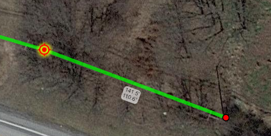
You can either use the dropper to click on the next location on the map or you can enter a set distance for the span. This will lock the connection to that distance so that you can then select the pole or location placement at that distance. You could also fill in a bearing to lock the angle as well.
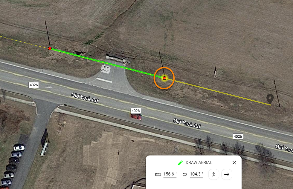
Once you left-click to add the second pole, the focus of the map shifts to the new pole. You can see a yellow highlight or halo around the location the drawing action will start from. Because the aerial tool was used, the connection_type attribute on the connection between the poles is automatically set to aerial. You can click on the connection at any time to change the connection_type if needed. You can also hold a left-click on the placed poles to move them. Releasing the click will set the position on the map.
When you are done using a specific mapping tool, you can switch to another tool using the new tool's shortcut or clicking the new tool within the toolset on the right side of the page.
You can also exit any selected drawing tool by hitting Escape ("Esc") on the keyboard, clicking the “X” within the window at the bottom, or right clicking on your mouse.

If you click on a location such as a pole, you will see three icons located under the item. The trashcan icon will delete that location (and consequently deleting any connections on it), the multi directional icon will move the item, and the pencil icon will open the Node Info panel for editing the node's data.

If span distances are turned on in your map labels (see above screenshot as reference for where to find this), you will also see the span distance and bearing label located under the connection. As you move a pole, this information will auto-update based on the new position.
At this point, click on the tool you need to use and make sure your map focus is on the correct starting location (make sure the location has a yellow highlight).
*If you don’t have a tool you need or think you will use on a regular basis, you can go into the Model Editor to make the tool and add it to the appropriate toolset.
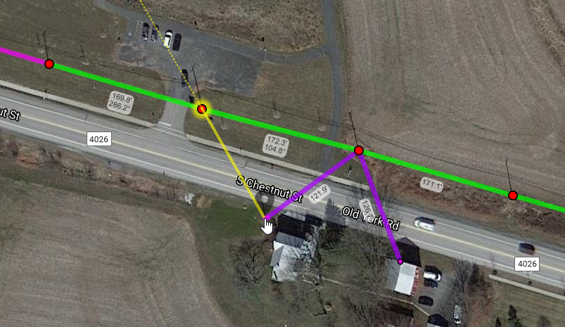
If multiple spans go to the same location, use the join tool so that you don’t add extra points to the map. Simply click your starting location, then choose which join tool you need to use.
Once you have a connection to draw, click the other location you need to join to. You will see the cursor turn into a pointing finger with a yellow line indicating where the connection will be placed; then you can left-click to place the connection and join the two locations.
Using Imported Layers
If you have a KMZ or shapefile, you can either bring those in as imported layers on the job to use for reference or use them to seed locations and connections onto the map. (You can also import reference layers via your company's default job model in the Model Editor so that these layers can be accessed by all jobs regardless of job model.)
File Imports

File imports allow you to import a KMZ or Shapefile into your job. These files should ideally be less than 5MB in size. Since they are at the job level, these imports can be seen on the mobile interface. If you wish to import a KMZ or Shapefile, in the Map Layers under "Imported Layers" is a "Manage Layers..." button. Click this to open the Manage Map Layers window.
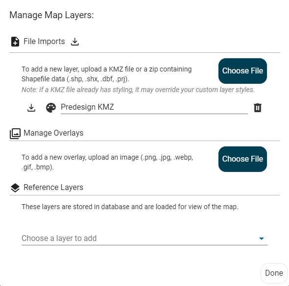
There's a section for File Imports where you can click "Choose File" to import. Any imported files can be downloaded, renamed, or deleted here. You can also change the styling of the KMZ or Shapefile here as well by clicking on the palette icon to the left of the file name.
Reference Layers
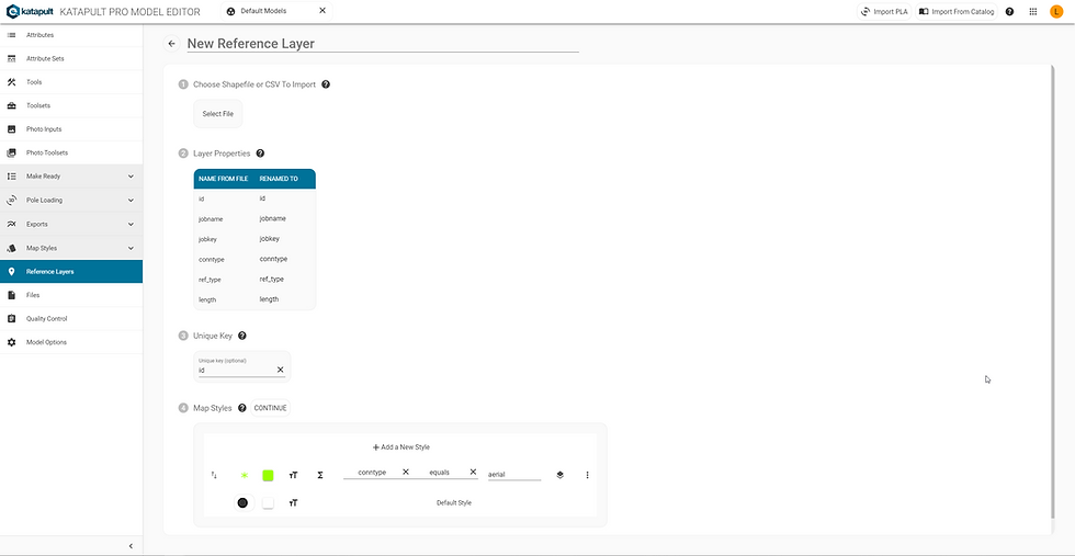
If you intend to use these files as reference layers to be accessed and referenced on any job, you'll want to go to the Model Editor and open your default job model (which usually shares the same name as your company) to upload your reference layer file. This file should be a Shapefile (zipped or unzipped, containing .shp, .dbf, and .prj files with point geometry) or a CSV file (which must contain "latitude" and "longitude" columns at minimum with valid EPSG:4326 coordinates). These files should be less than 10MB. You'll be able to add or remove properties, change the map styles, or adjust the advanced settings for the reference layer after it's created in the Model Editor.

Once you add a reference layer via the Model Editor, it is saved to the database. You can load it to the job by going to the "Manage Layers" under "Imported Layers" in the Map Layers. The "Manage Map Layers" window will appear (see above screenshot), and under the "Reference Layers" section, you'll find any reference layers stored in the database in the dropdown. Choose the layer(s) you want to include in the job. From the "Imported Layers" section in the Map Layers, you'll find the reference layer(s) and can turn them on and off or selectable or not.

If the File Import or Reference Layer is selectable, when you click on a section of the layer, you will see the various options for it. Here you can edit the description, change the colors, change the geometry, copy the feature, delete a feature within the layer, or copy nodes out to another job. If your field is a polygon, you can export by polygon (where if you have a polygon layer, any nodes found within the layer will be exported), or share by polygon (where any and all jobs that have nodes contained inside the polygon will be shared using the same sharing dialogue as the job Share button).

Once the layer is configured as needed, click the cursor to deselect the layer under "Imported Layers." This will enable you to place items directly over top or within the layer.

At this point, the design process would be the same as the basic method, where you can select the tools you need and draw locations directly onto the map.
Overlay Image

If you choose to add an image overlay to the map, make sure to pick one of the approved file types (.png, .jpg, .webp, .gif, or .bmp) that are less than 10MB. Click "Manage Layers" and then click the “Choose File” button under the "Manage Overlays" section and search for your file you want to add.
If you click on the image, a Katapult icon will appear. This anchor is a handle to move the overlay image around the map. If you need to rotate the image to match up, click on the photo again to add a second Katapult icon, the pointer, which can be used to rotate the image around or resize the image.
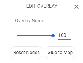
If you need to move the photo again or change the rotation nodes, click on the “Reset Nodes” button in the "EDIT OVERLAY" window at the bottom of the screen to start the process again.
In the "EDIT OVERLAY" window, you can name your overlay where it says "Overlay Name." You can also change the image’s opacity using the scroll bar in the middle. Once the image is set, click “Glue to Map” to finalize the image's placement. Now you can return to the Imported Layers to turn on the overlay file and predesign within or over the image overlay as needed.
If you forgot to name the Overlay, or wish to rename it, you can go to the "Manage Layers" under the "Imported Layers" section of the Map Layers menu, find the overlay underneath "Manage Overlays," and click the text to rename it. From here you can also delete the overlay.
Dragging Files Directly onto the Map
One of Katapult Pro’s easiest ways to predesign is to seed locations directly onto the map. You can drag a KMZ with pole locations onto the map, or you can generate a CSV file or spreadsheet of the locations with metadata and drag that file on the map.
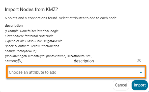
If you drag a KMZ or shapefile, the software will prompt you to choose attributes to add to the locations. If you are seeding poles, add the attribute node_type and select "pole" from the dropdown. You may also want to add other attributes to each location depending on what data you need.
If you have a spreadsheet with your pole or node data, you can drag that file directly on the map as well to seed in the poles with the metadata. The poles will be placed according to the latitude and longitude. Then you should define the node_type so that the locations are placed as the correct type. Then make sure any other data you want matches up to an attribute in your job model in Katapult Pro.
*At minimum there should be 'latitude' and 'longitude' columns or an 'address' column. If you are importing locations by address, we recommend using the full address (i.e. 19 N Baltimore St., Dillsburg, PA 17019).
As you can see, the attribute name will be the header located at the top of each column. If you do have data that doesn’t match a particular attribute, you will have an option to change it or have it map to something else when you drag the file onto the map.
You can use the dropdown menu to have the attribute map to something else or you can go into the Model Editor to add the attribute to the models then reupload the nodes.

Once the errors have been fixed, the “Add to Job” button will be available and the window will say “ Your data is ready to import!” The locations with the attribute data will then be seeded onto the map.
To import connections, you'll need the connection information in a separate CSV file. The bare minimum for your file with connections is to have two attributes that link the connection to two separate nodes that already exist in Katapult Pro as the connection's end points. These attributes should be unique to the node; no other node should have the same value for that attribute.
For example, you could use the pole tag of the nodes that are the connection's end points. As another example, you could use the SCID (sequentially coded identifier) of one node and the SCID of the other. (You'll need to make sure that you use the "Order" tool to assign SCIDs before importing connections if you are basing the endpoints on the node's SCID.)
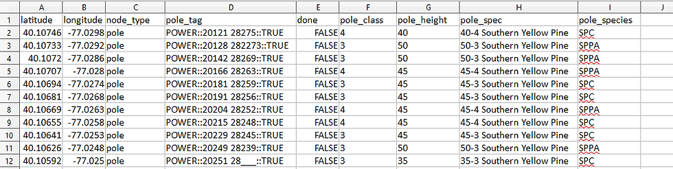
Below is a CSV file for 13 locations.

When this file is imported into Katapult Pro, the locations are seeded with attributes included (see screenshot below).

Note: the two reference nodes (SCID 001 and 013) are imported with all the same attributes that the poles are imported with. So even though they don't have values for pole_tag, done, pole_class, pole_height, pole_specs, or pole_species, those attributes are still added to those references. Most of them are blank, but they also have the "Done" attribute, which is a checkmark, and it's unchecked. That's why they look like red circles like the poles. Using the Multi-Edit Attribute tool to remove the "Done" attribute on reference nodes only will return them to the styling used for references.
To import the connections, we'll make two columns - 'scid1' and 'scid2' - to call out which nodes will be the endpoints of the connection. We'll add any other attributes we may want for the connections, such as 'connection_type.'

Note: just like the file for nodes, by including the 'reference_type' attribute in the file, it will be added to all connections. If I want to remove it from the aerial cables, I can use the "Multi-Edit Attribute" tool to remove the Reference Type attribute from connections that have the "aerial cable" connection type. (This is demonstrated in the GIF below.) I could also put all the aerial cables in a separate file from the reference connections and upload both files.
Once the file is dragged into the software, we're prompted to match a column from our file to an attribute on the node. (So the columns can be named whatever we want them to be; we just need to make sure we know which node attribute the software should be checking to find values on the nodes in Katapult Pro that correspond with the values in that column of our file.)
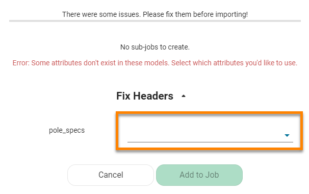
Finally, the software requires us to "Fix Headers;" in this case, I don't need the "scid1" and "scid2" columns to match any connection attributes. Since I can't "skip" those columns, I'll choose to match them to the "Note" attribute and remove them later using the Multi-Edit Attribute tool.
As far as formatting these CSV files correctly, below is an example CSV file (on the left) with the formatting for different kinds of attributes and how they will import into Katapult Pro (on the right) with the matching number (click on the photo to enlarge it). This is specifically for nodes, but a CSV file of connections will use the same formatting conventions.

Each row will be one node (or connection). Each column will represent attribute(s) for that node (or connection). Make sure the column headers are the names of the attributes in snake case (put all letters in lower case and replace spaces with an underscore, "_"). Values for the corresponding attributes should be as such (an asterisk "*" indicates a special system attribute specific to nodes):
*Latitude and longitude (1 and 2) - these have their own columns with their valid EPSG:4326 coordinate values in underneath. If you are using addresses instead, you'd use "address" as the column name with the address (the same way you would write it on a letter but on one line) underneath it. (This is required for importing nodes.)
*Pole Tag (11) - use the convention "[company name]::[tag text]::TRUE" or "[company name]::[tag text]::FALSE" where "[company name]" is the name of the company that corresponds with available values from the "Company" attribute dropdown, "[tag text]" is the information found on the tag, and "TRUE" or "FALSE" indicates whether that company is the pole owner or not.
Single Line Text attributes (including single line text with commit) (3 and 12) - enter the value of the attribute (and be sure to abide by any validation rules for the attribute, if there are any).
Hyperlink attributes (13) - enter the full URL of the hyperlink.
Multi-Line Text (15) - enter text; in Excel, you can hit Alt + Enter on your keyboard to add a new line.
Checkbox (8 and 9) - enter "true" or "false;" this is not case sensitive.
Dropdown (4, 14, 17, 18, 19) - enter a valid value (that corresponds to an available value in the dropdown list, typed as you see it in Katapult Pro)
Multi-Select Dropdown (21, 22, 23) - you will need a different column for each selected value, using the name of the attribute as the column header each time.
Table (5, 6, 7) - in the CSV column header, you will specify which table attribute you're using as well as which one of the table attribute's column headers you're referencing, separated by two colons "::". For each row in that table attribute's column, you will enter those values separated by a comma "," in the csv file.
In the above screenshot, for the "Manual Height" column in the "Clearance Range" attribute, this is formatted in F1 and F2 of the CSV file. So the column header is "clearance_range::manual_height," and the two values found in that column (31'-4", 23'-11"), are entered and separated by a comma (31'-4",23'-11"). The order of values listed for each column matters. Corresponding values should have the corresponding order in which they are listed.
Date (16) - the date must be in epoch unix timestamp format in milliseconds. (This is the milliseconds from January 1, 1970 to the date you're entering.)
File (10) - there isn't a way to import file(s) via a CSV file, but setting a value of 'true' for a file attribute will place that attribute, empty, on the node. The same is true for other attribute types that aren't checkboxes (23).
Once your locations are imported, you'll want to design the connections of those locations. You can either import them (as explained and demonstrated before), or you can design them directly in Katapult Pro.

If you switch your toolset to the Office Power Tools, there will be a tool called Join All Poles. You can use this as a quick option to join the poles together.
It will string the poles together in a single line using aerial connection. So if your route has multiple breaks or branching sections, or if you are not doing aerial work, it may be best not to use this tool.
You could also use the regular join option (found in the Aerial Design toolset) to start manually joining the nodes together. For this, click on your starting node, then click the join option you want, and click the next location to join the two with a connection.
Once your design is done, you are ready to send out the field crew to collect the data!
Helpful Reminders
If you click on a node or connection, the Node or Connection Info panel will be displayed on the right-hand side of the page. You can delete poles or connections by selecting the red “Delete” button at the bottom left of the Info panel. Deleting nodes will also delete any connections on that node.
You can also change the connection type or node type at any time by selecting the dropdown in the Node or Connection Info panel and finding the correct option. The available options in these picklists are edited in the Model Editor.
Feel free to modify tools to include multiple attributes on the draw action, especially with aerial tools. This allows you to avoid manually adding attributes in the Node or Connection Info panel each time you draw something.
You can use the Note tool to drop in notes to the field crew to make them aware of things to look for while at a particular location. This is a good way to communicate from office to field and vice versa.
If you can’t properly see a pole on the map, feel free to add an attribute such as “Verify Location in Field” to the Node Info. Give that attribute a styling to show that the field crew should confirm the location once at the pole. You can also switch or add Map Bases to make locating poles easier. (See below screenshot for an example of styling poles with the "Verify Location in Field" attribute.)
If you accidentally move a location, you can immediately press "Ctrl + Z” to undo the move on the map.
Use street view (see below screenshot for where to access this) to help locate poles or to see any taps or references coming off of a pole. It works identical to Streetview on Google Maps. As you move or rotate in street view, the pegman will rotate and move on the map so you can see exactly where you are. (Some areas may not have available Streetview.)

Aerial and Underground can be designed in the same job; make sure to switch to the proper toolset under the Tools dropdown when designing (or you can put them in the same toolset in the Model Editor).
Mobile will have the same capability and design functionality as desktop, so if design is needed from mobile, that is OK, just not recommended. Please refer to our Field Manual for more detail on using mobile.
Colors, styles, and icons can be adjusted using the Map Style Editor. Please refer to our Map Styles Manual for more information.
Thanks for reading! If you have any further questions, reach out to Support via support@katapultengineering.com or 717-430-0910. How can we improve our documentation? Let us know in the comments below!


Comments